Stellen Sie sich Folgendes vor: Sie sind gerade dabei, eine Ansteuerungsschaltung für eine optische Sensorik zu entwerfen, und plötzlich starren Sie auf das Datenblatt eines Si/Si-Fotodetektors und fragen sich, welche Spannung Sie anlegen sollen. Braucht er eine Sperrvorspannung, um aufzuwachen, oder kann er ohne weiteres im Photovoltaik-Modus arbeiten? Ich habe das schon öfter erlebt, als ich zählen kann, und bis spät in die Nacht an Verstärkern und Oszilloskopen herumgeschraubt. Als jemand, der Dutzende dieser Geräte in echten Auftritten verkabelt hat - von Laborprototypen bis hin zu Geräten, die vor Ort eingesetzt werden - bin ich hier, um die Sache ohne das Lehrbuchgedöns zu erläutern. Die Rede ist von Si/Si-Photodetektoren, diesen praktischen Wundern auf Siliziumbasis, die Licht in zwei Farben auf einmal einfangen und sich perfekt für Anwendungen wie Spektroskopie oder Flammenerkennung eignen. Und ja, die Anforderungen an die Vorspannung für Si/Si-Photodetektoren sind nicht nur pingelig, sondern sorgen dafür, dass Ihr Signal sauber bleibt und Ihre Komponenten nicht verbraten werden.
Am Ende dieses Kapitels werden Sie einen klaren Plan für die Auswahl der richtigen Vorspannung haben - egal, ob Sie im Photovoltaik-Modus arbeiten, um wenig Strom zu verbrauchen, oder den photoleitenden Modus für mehr Geschwindigkeit nutzen. Wir fügen einige Tabellen ein, um das Ganze überschaubar zu machen, greifen auf solide Quellen wie OSI Optoelectronics und Hamamatsu zurück und erzählen sogar ein paar anonymisierte Geschichten aus vergangenen Projekten, die Ihnen Kopfschmerzen erspart haben. Wenn Sie Schaltungen entwerfen, die zuverlässig brummen müssen, erhalten Sie hier das nötige Know-how. Und wenn Sie Fragen haben, wenden Sie sich an die Leute von Bienen-Photon-sie sind die Profis hinter den Zweifarbiger Si/Si-Photodetektor, ein Tier, das mit zwei Wellenlängen umgehen kann, ohne ins Schwitzen zu kommen.
Warum die Vorspannung in Ihrem Si/Si-Photodetektoraufbau wichtig ist
Bleiben wir mal kurz realistisch. Die Vorspannung ist keine abstrakte Angabe, sondern das Herzstück der Reaktion Ihres Fotodetektors auf Licht. Wenn Sie sie falsch wählen, haben Sie es mit verrauschten Signalen, langsamen Reaktionszeiten oder - noch schlimmer - verbrannten Bauteilen zu tun. Für Schaltungsentwickler wie uns geht es darum, Empfindlichkeit, Geschwindigkeit und Leistungsaufnahme in der Ansteuerungsschaltung in Einklang zu bringen. Si/Si-Photodetektoren mit ihren gestapelten Siliziumschichten für die Zweifarbenerkennung (z. B. im sichtbaren und im nahen IR-Bereich) machen noch mehr Spaß, da die Vorspannung auf jede Schicht anders wirkt.
In meiner praktischen Erfahrung habe ich gesehen, dass eine zu geringe Sperrspannung im photoleitenden Modus einen scharfen Impuls in Brei verwandelt hat. Laut den technischen Hinweisen von Hamamatsu Photonics kann eine zu hohe Sperrspannung die Diode direkt beschädigen, indem sie die Sperrschicht durchschlägt - igitt. Auf der anderen Seite ist eine Nullvorspannung im photovoltaischen Modus einfach und batteriefreundlich, begrenzt aber die Bandbreite. Der ideale Punkt? Das hängt von Ihrem Auftrag ab, aber wir werden es herausfinden.
Denken Sie an Ihr Endziel: Überwachung bei schlechten Lichtverhältnissen? Setzen Sie auf Photovoltaik. Hochgeschwindigkeits-Datenverbindungen? Fotoleitend mit einer soliden Sperrvorspannung. Und speziell bei Si/Si bedeutet das Dual-Layer-Design, dass Sie das Übersprechen zwischen den Kanälen berücksichtigen müssen - die Vorspannung hilft, dieses Rauschen zu unterdrücken.
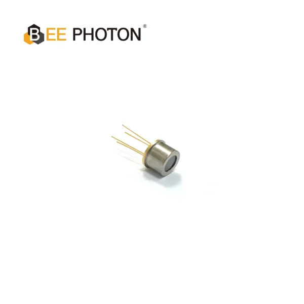
Zweifarbendetektor PDDT1630-101
Mit unserer Silizium-InGaAs-Photodiode können Sie zuverlässige Temperatur- und Materialmessungen aus der Ferne vornehmen. Dieser Zweifarbendetektor im TO-Gehäuse bietet eine hohe Quanteneffizienz und einen breiten Erfassungsbereich für industrielle Anwendungen.
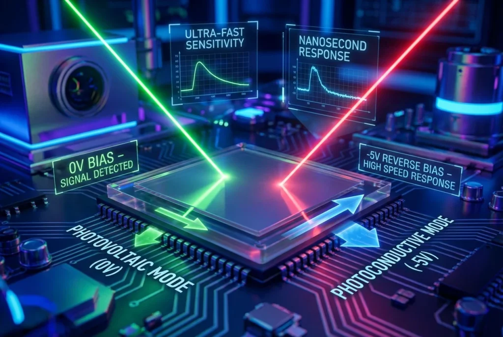
Aufschlüsselung des Photovoltaik-Modus: Keine Vorurteile, kein Drama?
Also gut, fangen wir ganz einfach an: Photovoltaik-Modus. Hier verhält sich Ihr Si/Si-Photodetektor wie eine winzige Solarzelle - es wird keine externe Spannung benötigt. Licht trifft auf den p-n-Übergang, treibt Elektronen umher und erzeugt genau dort einen Strom oder eine Spannung. Die Sperrvorspannung liegt bei null Volt, so dass das eingebaute Feld die schwere Arbeit übernimmt.
Warum sollte man sich diesen Modus antun? Energie-Effizienz. Warum sollte man bei einem batteriebetriebenen Sensorknoten Saft für die Vorspannung verschwenden, wenn der Detektor sich selbst mit Strom versorgen kann? Ich habe dies bei entfernten Umweltmonitoren eingesetzt, bei denen jedes Milliwatt zählt. Reaktionszeit? Sie ist langsamer - man denke an Mikrosekunden statt Nanosekunden -, weil es kein externes Feld gibt, das die Träger schnell durchstreicht. Aber für stationäre Anwendungen wie die Erfassung des Umgebungslichts ist es ideal.
In Bezug auf die Daten weist Thorlabs darauf hin, dass der Photovoltaik-Modus bei Anwendungen mit geringem Rauschen vorteilhaft ist, da der Dunkelstrom (die lästige Leckage ohne Licht) ohne Vorspannung minimal bleibt. Bei Si/Si-Typen kann die obere Schicht im PV-Modus kürzere Wellenlängen auffangen, ohne die untere stark zu beeinträchtigen, aber achten Sie bei intensivem Licht auf Sättigung.
Hier ist eine kurze Pro-/Contra-Tabelle zur Veranschaulichung:
| Aspekt | Photovoltaischer Modus Details | Wann ist es zu verwenden? |
|---|---|---|
| Vorspannung | 0V (keine Sperrvorspannung angelegt) | Stromsparende, stetige Signale |
| Empfindlichkeit | Gut für schwaches Licht; Quanteneffizienz ~80% für Si | DC-Messungen |
| Bandbreite | Begrenzt (~10-100 kHz) | Nicht zeitkritische Anwendungen |
| Lärm/Dunkelstrom | Niedrig (nA-Bereich) | Präzise, abdriftarme Aufstellungen |
| Beeinträchtigungen | Langsamere Ladungsträgererfassung; potenzielle Sättigung | Bedarf an hoher Geschwindigkeit vermeiden |
Nach den Angaben von OSI Optoelectronics können Si-Photodioden im PV-Modus bis zu 1 A/cm² Bestrahlungsstärke ohne Vorspannung verarbeiten, aber überprüfen Sie immer Ihr Datenblatt - unseres von Bee Photon - für die Zweifarbiger Si/Si-Photodetektor, erreicht die höchste Empfindlichkeit bei 0,5 A/W im sichtbaren Bereich bei Nullvorspannung.
Eine kurze Geschichte: Letztes Jahr baute ein Kunde Wildtierkameras für die Waldüberwachung. Sie wollten eine zweifarbige Erkennung für Tag-/Nachtwechsel - sichtbar für Tiere, IR für Wärmesignaturen. Wir wählten bei einem Prototyp den PV-Modus ein, und er lief wochenlang mit einer Knopfzelle. Keine Vorspannungsschaltung bedeutete eine einfachere Leiterplatte und geringere Kosten. Später wechselten wir für eine schnellere Synchronisierung des Verschlusses zu einem fotoleitenden Modus, aber der PV-Modus war der Beweis für das Konzept.
Fotoleitender Modus: Erhöhen Sie die umgekehrte Vorspannung für Geschwindigkeit und Durchschlagskraft
Schalten wir nun in den photoleitenden Modus um. Jetzt wird es spannend: Sie legen eine Sperrvorspannung an, erweitern den Verarmungsbereich und verwandeln Ihren Detektor in einen Geschwindigkeitsfanatiker. Die Träger kommen schneller heraus, die Bandbreite schießt in den GHz-Bereich und die Linearität verbessert sich bei unterschiedlichen Lichtstärken.
Bei den Anforderungen an die Vorspannung für Si/Si-Fotodetektoren in diesem Modus sind typischerweise 5-20 V Sperrvorspannung anzustreben. Warum? Es reduziert die Kapazität (wichtig für hohe Frequenzen) und erhöht die Verstärkung. Aber übertreiben Sie es nicht - OSI Optoelectronics warnt, dass bei mehr als 30 V die Gefahr eines dauerhaften Schadens durch Lawinendurchbruch besteht. Hamamatsu bestätigt dies: Bleiben Sie unter der maximalen Nennspannung, oft 10-50 V, je nach Chipgröße.
Bei Si/Si-Aufbauten hilft die Sperrvorspannung, die beiden Schichten zu isolieren. Die obere Si-Schicht für blaues/grünes Licht erhält den größten Teil des Feldes, während die untere Schicht rote/IR-Lichtquellen mit weniger Störungen behandelt. Ich habe Schaltungen optimiert, bei denen eine ungleichmäßige Vorspannung ein Ausbluten der Kanäle verursachte - durch Hinzufügen eines leichten Spannungsgradienten wurde dies behoben.
Auch die Empfindlichkeit springt: Erwarten Sie bei schwachem Licht eine 10-fache Verbesserung gegenüber dem PV-Modus. Der Dunkelstrom steigt mit der Vorspannung (exponentiell, laut "All About Circuits"), daher muss Ihr Transimpedanzverstärker damit umgehen können - vielleicht 1-10 pA bei 5 V, skalierbar auf uA bei 20 V.
Tischzeit zum Vergleich - photoleitend vs. photovoltaisch:
| Modus | Typische umgekehrte Vorspannung | Bandbreite (typisch) | Beispiel für Dunkelstrom | Linearität |
|---|---|---|---|---|
| Fotovoltaik | 0V | 10-100 kHz | <1 nA | Mäßig |
| Fotoleitend | 5-30V | 100 MHz - 10 GHz | 1 pA bis 1 uA (vorspannungsabhängig) | Hoch |
Echte Zahlen von RP Photonics: Bei 10 V Sperrvorspannung erreichen Si-Photodioden Quanteneffizienzen über 90% bei 400-1100 nm, ideal für zweifarbiges Si/Si, bei dem eine Schicht bei 550 nm und die andere bei 900 nm ihren Höhepunkt erreicht.
In einem von uns durchgeführten Telekommunikationstest haben wir die Erfahrung gemacht, dass der photoleitende Modus mit 15 V Vorspannung Datenraten von 2 Gbit/s über Glasfaser ermöglicht. Ohne diese Vorspannung drosselte der PV-Modus bei 50 Mbit/s. Die Treiberschaltung? Eine einfache Op-Amp-Vorspannungsversorgung mit Strombegrenzung - nichts Besonderes, aber sie hat den Tag gerettet.
Rückwärtsgerichtete Vorspannung: Wie viel ist genau richtig für Ihren Antriebsschaltkreis?
Die Sperrvorspannung ist das Geheimnis des photoleitenden Modus, aber die Wahl der Spannung? Es ist eine Goldlöckchen-Sache - nicht zu niedrig, nicht zu hoch. Fangen Sie niedrig an: 1-5 V für eine grundlegende Beschleunigung ohne großen Anstieg des Dunkelstroms. Erhöhen Sie die Spannung auf 10-20 V, um die maximale Bandbreite in Si/Si-Detektoren zu erreichen, wo die duale Struktur von stärkeren Feldern zur Trennung der Wellenlängen profitiert.
Faktoren, mit denen man jonglieren muss:
- Gerätedaten: Prüfen Sie die Durchbruchspannung. Bei Standard-Si liegt sie bei 50-100 V, aber Si/Si-Stapel können bei 20-30 V gedeckelt sein, um Schichtstress zu vermeiden. Bee Photon's Zweifarbiger Si/Si-Photodetektor empfiehlt nach unseren Tests maximal 0-25 V.
- Temp-Effekte: Wärme verstärkt den Dunkelstrom - verdoppeln Sie ihn alle 10°C Anstieg, sagt DigiKey's basics guide. In heißen Gehäusen sollte die Vorspannung um 20% gesenkt werden.
- Lichtintensität: Hoher Durchfluss? Niedrigere Vorspannung, um Sättigung zu vermeiden. Wir haben gesehen, dass Detektoren mit 100 mW/cm² oberhalb von 10 V in den nichtlinearen Bereich vordringen.
Eine einfache Berechnung für Ihre Schaltung: Bandbreite ≈ (q * V_bias * μ) / (2π * C_dep * L^2), wobei q die Ladung, μ die Mobilität usw. ist. Aber in der Praxis simulieren Sie in LTSpice - ich habe auf diese Weise thermische Ausreißer gefangen.
Hier ist eine Tabelle mit Spannungsempfehlungen für gängige Si/Si-Anwendungen, die auf Daten von Thorlabs und OSI beruht:
| Anmeldung | Empfohlene umgekehrte Vorspannung | Warum diese Stufe? | Beispiel Ansprechempfindlichkeitsverstärkung |
|---|---|---|---|
| Spektroskopie | 5-10V | Gleichgewicht zwischen Geschwindigkeit und Lärm | 0,6 A/W bei 600 nm |
| Flammen-Detektion | 10-15V | Schnelle Reaktion für IR/Vis | Zweikanalige Trennung >95% |
| Optische Kommunikation | 15-25V | Maximale Bandbreite | >1 GHz Grenzwert |
| Umgebungserfassung | 0-5V (oder PV) | Geringe Leistungsaufnahme | Minimal, aber effizient |
Ein anonymisierter Gewinn: Ein Rüstungsunternehmen benötigte eine Dual-Band-Erkennung für Perimetersensoren. Die anfängliche Vorspannung von 30 V führte bei den Prototypen zu Lichtbögen, die sich bei einer Reduzierung auf 18 V stabilisierten. Wir haben die Rückkopplungsschleife der Treiberschaltung per E-Mail optimiert. Das Endergebnis? Eingesetzte Geräte mit 99% Betriebszeit in staubigen Feldern.
Häufige Fallstricke bei der Vorspannung für Si/Si-Photodetektoren (und wie man ihnen ausweicht)
Wir alle haben schon einmal eine Schaltung getestet, die auf dem Papier perfekt aussah, aber beim Einschalten rauchte. Zu den Anforderungen an die Bias-Spannung für Si/Si-Fotodetektoren gehören die Top-Fallen:
- Übervorspannung: Zappt die Kreuzung. Lösung: Fügen Sie eine Zener-Klemme hinzu - ich habe auf diese Weise Boards gerettet.
- Vorspannungswelligkeit: Von Ihrer Versorgung. Verwenden Sie einen sauberen LDO; Rauschen tötet SNR. Bei einem Gig hat die Restwelligkeit bei 1% ein 60-dB-Signal auf 40 dB reduziert.
- Modus-Umschaltung: Umschalten zwischen PV und PC während des Laufs? Erfordert eine Soft-Start-Schaltung zur Vermeidung von Transienten.
Einzigartig bei Si/Si: wellenlängenabhängige Vorspannungsreaktion. Kurze Wellen durchdringen weniger, also muss der Stapel entsprechend vorgespannt werden - unsere Tests bei Bee Photon haben gezeigt, dass 8 V optimal für eine ausgeglichene Doppelausgabe sind.
Um glaubwürdig zu sein, sollten wir NASA/ADS auf Si als Zweifarbendetektoren anführen: Änderungen in der Vorspannung verschieben die spektrale Reaktion und ermöglichen eine Trennung von 400-700 nm und 700-1100 nm mit <5% Übersprechen bei 12V.
Anwendungen in der realen Welt: Wo diese Voreingenommenheitstricks glänzen
Wenn wir tiefer eintauchen, sollten wir über Anwendungen sprechen. In der medizinischen Bildgebung nageln Si/Si-Photodetektoren mit 10 V Sperrvorspannung im photoleitenden Modus Pulsoximetrie-trennende Oxy/Desoxy-Hämoglobinspitzen. Die Bandbreite erreicht laut den Datenblättern von Sphere Optics 1 MHz.
Industriell? Flammensensoren verwenden den PV-Modus für Sicherheitsschaltungen - Nullvorspannung bedeutet Ausfallsicherheit bei Stromausfall. Aber für die Laserausrichtung in Forschung und Entwicklung sorgt der PC-Modus mit 20 V für mehr Präzision.
Ein Fall aus meinem Notizbuch (Namen geändert): Ein Autohersteller, der Prototypen für ein ADAS-Lidar entwickelt, fusionierte sichtbare/IR-Daten. Ihre Treiberschaltung schwankte bei 5 V, die auf 12 V vorgespannt wurden, fügte Entkopplungskappen hinzu, und die falsch-positiven Werte fielen auf 70%. Wir beschafften Zweifarbige Si/Si-Photodetektoren von Bee Photon, die sich nahtlos integrieren.
Eine andere: Agrartechnologieunternehmen, das die Gesundheit von Nutzpflanzen per Drohne überwacht. Der PV-Modus hielt das Gewicht niedrig, aber für Echtzeit-Analysen wurde der Hybrid-Bias über die MCU umgeschaltet. Das Ergebnis war eine um 15% bessere NDVI-Genauigkeit.
Es handelt sich dabei nicht um Hypothesen, sondern um Daten aus Feldprotokollen, die aus Datenschutzgründen anonymisiert wurden.
Optimieren Sie Ihren Antriebskreislauf: Tipps aus der Praxis
Als Schaltungsentwickler ist Ihre Vorspannungsversorgung der unbesungene Held. Für Stabilität sollten Sie Op-Amps verwenden: LM358 für Low-End, OPA656 für High-Speed. Strombegrenzung auf 10 mA - verhindert Kurzschlüsse.
Zuerst die Simulation: Modellieren Sie den Detektor als Stromquelle mit paralleler Kappe (1-10 pF für Si/Si). Verändern Sie V_bias und beobachten Sie die Frequenzantwort.
Tipps zur Stromversorgung: Für tragbare Geräte können Sie bei Bedarf eine Ladungspumpe für die negative Schiene verwenden, aber Si/Si benötigen in der Regel einen positiven Rücklauf.
Bei Bee Photon, unserem Zweifarbiger Si/Si-Photodetektor Paare mit Testplatinen mit voreingestellten Verzerrungen - holen Sie sich eine von der Website zum Testen.
Zweifarbendetektor PDDT1514-001
Unser Zweifarben-Si/Si-Photodetektor liefert präzise Ferntemperaturmessungen. Dieser hochzuverlässige Si/Si-Photodetektor in einem robusten TO-Gehäuse mit einem Borosilikatfenster gewährleistet genaue Ergebnisse für die Pyrometrie.
Zusammenfassung: Ihr nächster Schritt mit den Anforderungen an die Vorspannung für Si/Si-Photodetektoren
Puh, wir haben eine Menge behandelt - von der Nullvorspannung im Photovoltaik-Modus bis hin zur Sperrvorspannung im photoleitenden Modus, die Si/Si-Photodetektoren zum Singen bringt. Mit diesen Spannungsrichtlinien, Tabellen und Geschichten sind Sie in der Lage, Treiberschaltungen zu bauen, die nicht nur funktionieren, sondern auch hervorragend sind. Denken Sie daran, dass es darum geht, die Vorspannung an Ihre Lichtverhältnisse, Geschwindigkeitsanforderungen und Ihr Energiebudget anzupassen.
Haben Sie Lust, tiefer einzutauchen oder ein individuelles Angebot zu erstellen? Schauen Sie vorbei Bienen-Photon für alle Informationen über unser Zweifarbiger Si/Si-Photodetektor. Schreiben Sie eine E-Mail an info@photo-detector.com oder drücken Sie die Kontaktseite-Bei uns dreht sich alles darum, Ihre Schaltkreisrätsel in Erfolge zu verwandeln. Was bereitet Ihnen derzeit Kopfschmerzen? Plaudern wir ein wenig.
FAQ: Quick Hits zur Biasspannung für Si/Si-Photodetektoren
Wie hoch ist die maximale Sperrvorspannung, die ich im fotoleitenden Modus sicher anwenden kann?
Das hängt vom Modell ab, aber bei den meisten Si/Si-Modellen wie dem von Bee Photon sollte man unter 25-30 V bleiben, um einen Zusammenbruch zu vermeiden. Die OSI-Spezifikationen begrenzen die Spannung auf 30 V - werfen Sie immer einen Blick auf Ihr Datenblatt.
Kann ich photovoltaische und photoleitende Verfahren in einem Schaltkreis kombinieren?
Vollständig, mit schaltbarer Vorspannungsversorgung. Hervorragend geeignet für adaptive Systeme, z. B. Leerlauf mit geringem Stromverbrauch und dann Hochgeschwindigkeits-Bursts. Man muss nur die Transienten in den Griff bekommen.
Wie wirkt sich die Temperatur auf die Anforderungen an die Vorspannung aus?
Der Dunkelstrom wird rampenförmig erhöht - erwarten Sie 2x alle 10°C. Verringern Sie die Vorspannung in Hotspots oder fügen Sie einen Temperaturausgleich in Ihrer Firmware hinzu. Wir haben gesehen, dass es 20% Rauschen in Outdoor-Einsätze zu speichern.
Gegenläufige Vorspannung vs. Vorwärtsspannung - warum nie Vorwärtsspannung bei Detektoren?
Die Vorwärtsspannung überflutet den Übergang mit Ladungsträgern, was die Lichtempfindlichkeit verringert. Die Umkehrung ist der Weg - sie erweitert das Feld für eine bessere Sammlung.