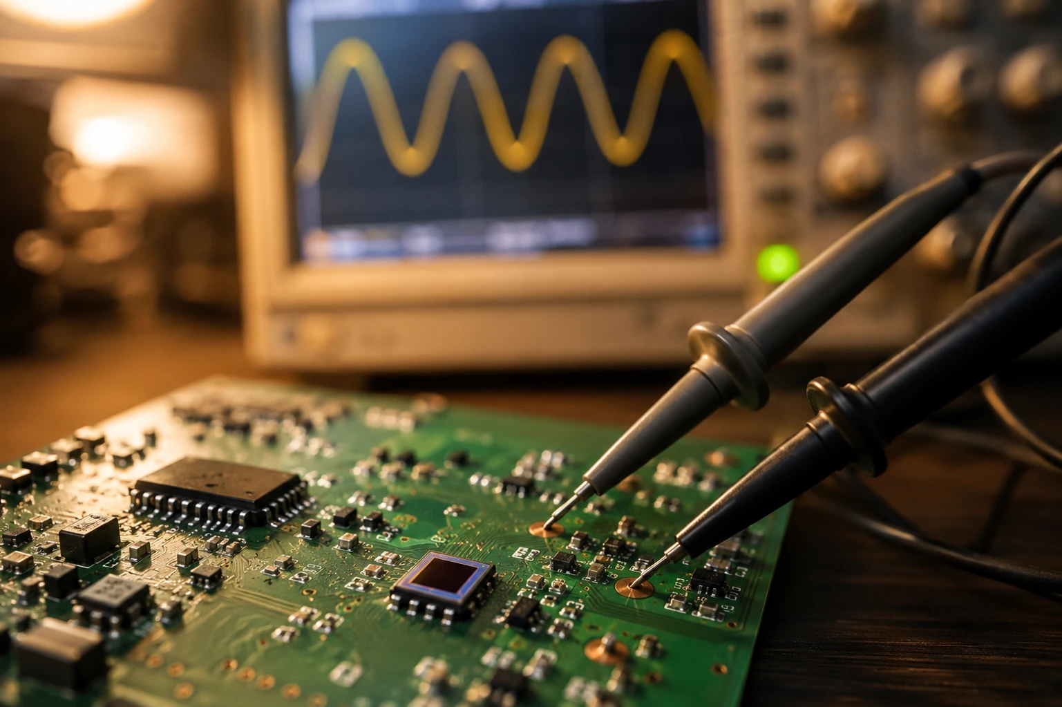
Imagínatelo: estás inmerso en el diseño de un circuito de accionamiento para un sistema de detección óptica y, de repente, te encuentras mirando la hoja de datos de un fotodetector de Si/Si y no sabes qué voltaje aplicarle. ¿Necesita una polarización inversa para despertarse o puede funcionar en modo fotovoltaico sin problemas? He estado allí más veces de las que puedo contar, ajustando amplificadores y osciloscopios hasta altas horas de la noche. Como alguien que ha cableado docenas de estos equipos en actuaciones reales -desde prototipos de laboratorio hasta equipos desplegados sobre el terreno- estoy aquí para explicarlo sin el zumbido de los libros de texto. Estamos hablando de fotodetectores Si/Si, esas prácticas maravillas basadas en el silicio que captan la luz en dos colores a la vez, perfectas para aplicaciones como la espectroscopia o la detección de llamas. Y sí, cumplir los requisitos de voltaje de polarización de los fotodetectores de Si/Si no es sólo un detalle; es lo que mantiene limpia la señal y evita que se frían los componentes.
Al final, tendrás un mapa claro para elegir la polarización adecuada, tanto si utilizas el modo fotovoltaico para obtener vibraciones de baja potencia como si utilizas el modo fotoconductor para obtener velocidad. Incluiremos algunas tablas para facilitar la lectura, recurriremos a fuentes sólidas como OSI Optoelectronics y Hamamatsu, e incluso compartiremos un par de historias anónimas de proyectos anteriores que nos han ahorrado dolores de cabeza. Si estás diseñando circuitos que necesitan zumbar de forma fiable, esto te proporcionará los conocimientos necesarios. Y si le surgen preguntas, póngase en contacto con la gente de Fotón abeja-son los profesionales detrás del Fotodetector Si/Si bicolor, una bestia que maneja longitudes de onda duales sin sudar.
Por qué es importante la tensión de polarización en la configuración del fotodetector Si/Si
Seamos realistas. El voltaje de polarización no es una especificación abstracta; es el latido del corazón de cómo tu fotodetector responde a la luz. Si se equivoca, se encontrará con señales ruidosas, tiempos de respuesta lentos o, lo que es peor, piezas quemadas. Para los diseñadores de circuitos como nosotros, se trata de equilibrar la sensibilidad, la velocidad y el consumo de energía en el circuito de accionamiento. Los fotodetectores Si/Si, con sus capas de silicio apiladas para la detección de dos colores (visible e infrarrojo cercano), añaden un nivel de diversión porque la polarización afecta a cada capa de forma diferente.
En mi experiencia práctica, he visto configuraciones en las que el escatimar en la polarización inversa en el modo fotoconductor convertía un pulso nítido en papilla. Según las notas técnicas de Hamamatsu Photonics, una tensión inversa excesiva puede dañar directamente el diodo al perforar la unión. Por otro lado, la polarización cero en modo fotovoltaico simplifica las cosas y ahorra batería, pero limita el ancho de banda. ¿El punto óptimo? Depende de tu actuación, pero vamos a trazarlo.
Piense en su objetivo final: ¿vigilancia con poca luz? Opte por la fotovoltaica. ¿Enlaces de datos de alta velocidad? Fotoconductores con una polarización inversa sólida. Y en el caso concreto del Si/Si, ese diseño de doble capa significa que hay que tener en cuenta la diafonía entre canales: el polarizado ayuda a suprimir ese ruido.
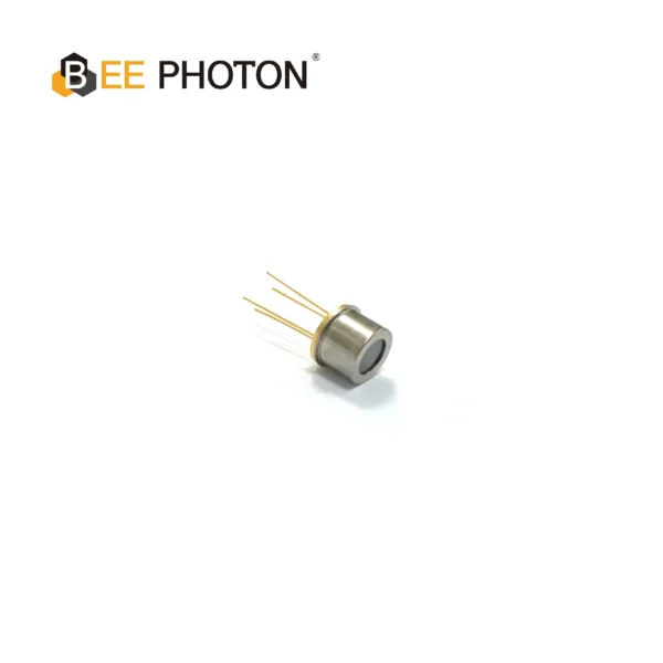
Detector bicolor PDDT1630-101
Consiga una detección remota fiable de temperatura y materiales con nuestro fotodiodo de Silicio-InGaAs. Este detector bicolor empaquetado en TO ofrece una alta eficiencia cuántica y un amplio rango de detección para aplicaciones industriales.
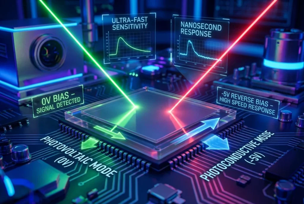
Desmontando el modo fotovoltaico: ¿Cero prejuicios, cero dramas?
Muy bien, empezando por lo más sencillo: el modo fotovoltaico. En este modo, el fotodetector de Si/Si actúa como una pequeña célula solar, sin necesidad de tensión externa. La luz incide en la unión p-n, mueve los electrones y genera una corriente o tensión allí mismo. Es polarización inversa a cero voltios, básicamente dejando que el campo incorporado haga el trabajo pesado.
¿Por qué este modo? Eficiencia energética. En un nodo sensor alimentado por batería, ¿por qué gastar energía en polarización cuando el detector puede autoalimentarse? Lo he utilizado en monitores medioambientales remotos donde cada milivatio cuenta. ¿Tiempo de respuesta? Es más lento -piensa en microsegundos en lugar de nanosegundos- porque no hay un campo externo que barra los portadores rápidamente. Pero para cosas estables, como la detección de la luz ambiental, es de oro.
En cuanto a los datos, Thorlabs señala que el modo fotovoltaico brilla en aplicaciones con poco ruido, ya que la corriente oscura (esa molesta fuga sin luz) es mínima sin polarización. En los tipos Si/Si, la capa superior puede captar longitudes de onda más cortas en modo fotovoltaico sin afectar demasiado a la inferior, pero hay que tener cuidado con la saturación si la luz es intensa.
He aquí una rápida tabla de pros y contras para visualizar:
| Aspecto | Detalles del modo fotovoltaico | Cuándo utilizarlo |
|---|---|---|
| Tensión de polarización | 0V (sin polarización inversa aplicada) | Señales constantes de bajo consumo |
| Sensibilidad | Buena para poca luz; eficiencia cuántica ~80% para Si | Mediciones de CC |
| Ancho de banda | Limitado (~10-100 kHz) | Aplicaciones no críticas |
| Ruido/Corriente oscura | Bajo (rango nA) | Ajustes de precisión y baja deriva |
| Inconvenientes | Recogida más lenta del portador; saturación potencial | Evitar las necesidades de alta velocidad |
Según las especificaciones de OSI Optoelectronics, los fotodiodos de Si en modo fotovoltaico soportan hasta 1A/cm² de irradiancia sin polarización, pero compruebe siempre su hoja de datos (la nuestra en Bee Photon, para la Fotodetector Si/Si bicolor, alcanza un máximo de 0,5 A/W en la banda visible con polarización cero.
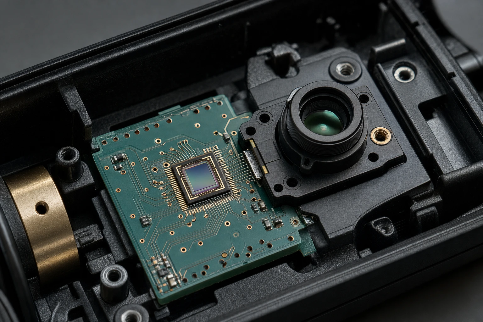
Una anécdota: El año pasado, un cliente estaba construyendo cámaras para la vigilancia de la fauna salvaje en los bosques. Querían detección bicolor para los cambios de día y noche: visible para los bichos e IR para las señales de calor. Seleccionamos el modo fotovoltaico en un prototipo y funcionó durante semanas con una pila de botón. Al no tener circuitos de polarización, la placa de circuito impreso era más sencilla y menos costosa. Más tarde cambiamos a fotoconductor para acelerar la sincronización del obturador, pero el modo fotovoltaico fue la prueba de concepto.
Modo fotoconductor: Aumenta la polarización inversa para conseguir velocidad y pegada
Pasemos ahora al modo fotoconductor. Aquí es donde las cosas se ponen emocionantes: se aplica una polarización inversa, ampliando la región de agotamiento y convirtiendo el detector en un demonio de la velocidad. Las portadoras salen más rápido, el ancho de banda se dispara hasta el territorio de los GHz y la linealidad mejora para esos niveles de luz variables.
En cuanto a los requisitos de tensión de polarización para fotodetectores Si/Si en este modo, el objetivo suele ser una polarización inversa de 5-20 V. ¿Por qué? Reduce la capacitancia (clave para frecuencias altas) y aumenta la ganancia. Pero no hay que volverse loco: OSI Optoelectronics advierte de que a más de 30 V se corre el riesgo de sufrir daños permanentes por ruptura de avalancha. Hamamatsu se hace eco de esta advertencia: no sobrepase el valor nominal máximo, que suele ser de 10-50 V en función del tamaño de la matriz.
En las configuraciones Si/Si, la polarización inversa ayuda a aislar las dos capas. La capa superior de Si para la luz azul/verde recibe la mayor parte del campo, mientras que la inferior maneja el rojo/IR con menos interferencias. He ajustado circuitos en los que una polarización desigual provocaba el sangrado de los canales.
La sensibilidad también aumenta: es 10 veces mejor que el modo FV con poca luz. La corriente oscura aumenta con la polarización (de forma exponencial, según All About Circuits), por lo que el amplificador de transimpedancia debe ser capaz de manejarla: quizá de 1 a 10 pA a 5 V, escalando a uA a 20 V.
Tabla horaria para comparación-fotoconductor vs. fotovoltaico:
| Modo | Sesgo inverso típico | Ancho de banda (típico) | Ejemplo de corriente oscura | Linealidad |
|---|---|---|---|---|
| Fotovoltaica | 0V | 10-100 kHz | <1 nA | Moderado |
| Fotoconductor | 5-30V | 100 MHz - 10 GHz | 1 pA a 1 uA (en función de la polarización) | Alta |
Cifras reales de RP Photonics: Con una polarización inversa de 10 V, los fotodiodos de Si alcanzan eficiencias cuánticas superiores a 90% entre 400 y 1100 nm, ideales para Si/Si de dos colores en los que una capa alcanza un pico a 550 nm y la otra a 900 nm.
Por experiencia, en un banco de pruebas de telecomunicaciones que hicimos, el modo fotoconductor con una polarización de 15 V nos permitió registrar velocidades de datos de 2 Gbps por fibra. Sin ella, el modo FV se ahogaba a 50 Mbps. ¿El circuito de accionamiento? Un básico op-amp con limitación de corriente, nada del otro mundo, pero nos salvó el día.
La polarización inversa: ¿cuánta es la adecuada para su circuito de accionamiento?
La polarización inversa es el secreto del modo fotoconductor, pero ¿hay que elegir el voltaje? Es una cuestión de ricitos de oro: ni demasiado bajo ni demasiado alto. Empieza por bajo: 1-5V para una aceleración básica sin mucho aumento de la corriente oscura. Aumente a 10-20 V para obtener el máximo ancho de banda en detectores Si/Si, donde la estructura dual se beneficia de campos más intensos para separar las longitudes de onda.
Factores a tener en cuenta:
- Especificaciones del dispositivo: Comprueba el voltaje de ruptura. Para el Si estándar, es de 50-100V, pero las pilas de Si/Si pueden tener un límite de 20-30V para evitar la tensión en las capas. Fotón de abeja Fotodetector Si/Si bicolor recomienda 0-25V máximo, según nuestras pruebas.
- Efectos Temp: El calor amplifica la corriente oscura: duplíquela cada 10 °C de aumento, según la guía básica de DigiKey. En recintos calientes, reduzca la polarización en 20%.
- Intensidad de la luz: ¿Flujo alto? Baja la polarización para evitar la saturación. Hemos visto detectores de 100 mW/cm² entrar en territorio no lineal por encima de 10 V.
Un simple calc para tu circuito: Ancho de banda ≈ (q * V_bias * μ) / (2π * C_dep * L^2), donde q es carga, μ movilidad, etc. Pero en la práctica, simular en LTSpice-He cogido fugas térmicas de esa manera.
He aquí una tabla de recomendaciones de voltaje basada en las aplicaciones comunes de Si/Si, extraída de los datos de Thorlabs y OSI:
| Aplicación | Sesgo inverso recomendado | ¿Por qué este nivel? | Ejemplo Ganancia de respuesta |
|---|---|---|---|
| Espectroscopia | 5-10V | Equilibra velocidad y ruido | 0,6 A/W a 600 nm |
| Detección de llama | 10-15V | Respuesta rápida para IR/Vis | Separación de dos canales >95% |
| Comunicaciones ópticas | 15-25V | Ancho de banda máximo | Corte >1 GHz |
| Sensores ambientales | 0-5V (o PV) | Bajo consumo | Mínimo, pero eficaz |
Una victoria anónima: Un contratista de defensa necesitaba detección de doble banda para sensores perimetrales. Su polarización inicial de 30 V provocó la formación de arcos en los prototipos, que bajaron a 18 V y se estabilizaron. Repetimos la operación por correo electrónico, ajustando el bucle de realimentación del circuito de accionamiento. ¿Resultado final? Unidades desplegadas con 99% en campos polvorientos.
Errores comunes en el voltaje de polarización para fotodetectores Si/Si (y cómo evitarlos)
Mira, todos hemos montado alguna vez un circuito que parecía perfecto sobre el papel, pero que echaba humo al encenderlo. Para los requisitos de voltaje de polarización para fotodetectores Si/Si, las mejores trampas incluyen:
- Exceso de prejuicios: Zafa la unión. Solución: Añade una pinza zener; he salvado placas así.
- Rizado de polarización: De tu fuente. Usa un LDO limpio; el ruido mata la SNR. En un concierto, el rizado a 1% redujo una señal de 60 dB a 40 dB.
- Cambio de modo: ¿Cambio entre FV y PC a mitad de carrera? Necesita un circuito de arranque suave para evitar transitorios.
Exclusivo de Si/Si: respuesta de polarización dependiente de la longitud de onda. Las ondas cortas penetran menos, por lo que hay que polarizar la pila en consecuencia. Nuestras pruebas en Bee Photon demostraron que 8 V es lo óptimo para una salida dual equilibrada.
Para mayor fiabilidad, citemos a la NASA/ADS en Si como detectores de dos colores: Cambios en la respuesta espectral por desplazamiento de polarización, lo que permite una separación de 400-700 nm y 700-1100 nm con una diafonía <5% a 12V.
Aplicaciones reales: Dónde brillan estos trucos de sesgo
Profundizando, hablemos de aplicaciones. En imágenes médicas, los fotodetectores de Si/Si con polarización inversa de 10 V en modo fotoconductor clavan los picos de hemoglobina oxi/desoxi en la oximetría de pulsos. El ancho de banda alcanza 1 MHz, según las hojas de datos de Sphere Optics.
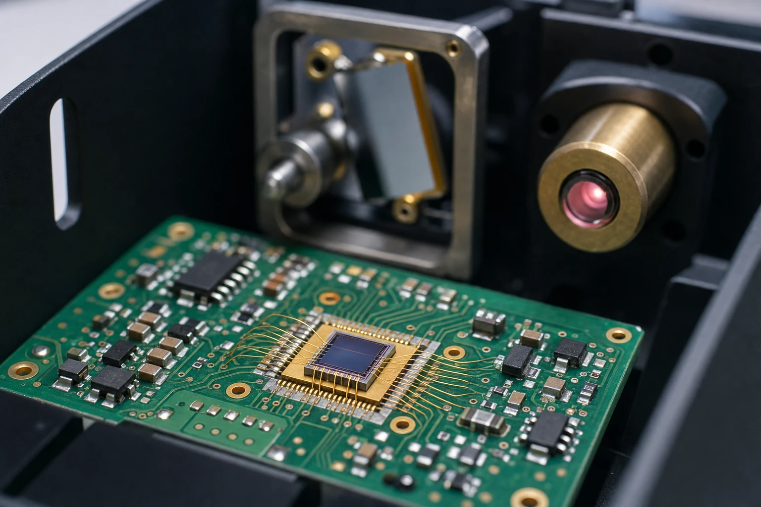
¿Industrial? Los sensores de llama utilizan el modo FV para los circuitos de seguridad (polarización cero en caso de caída de tensión). Pero para la alineación láser en I+D, el modo PC con 20 V aumenta la precisión.
Un caso de mi cuaderno (nombres ficticios): Un fabricante de automóviles prototipos ADAS lidar fusionado datos visibles / IR. Su circuito de accionamiento oscilaba a 5 V, pero lo cambiaron a 12 V, añadieron cápsulas de desacoplamiento y los falsos positivos se redujeron a 70%. Obtuvimos Fotodetectores de Si/Si de dos colores de Bee Photon, integrándose a la perfección.
Otro: Una empresa de tecnología agrícola que controla la salud de los cultivos con un dron. El modo fotovoltaico mantenía el peso bajo, pero para los análisis en tiempo real, el cambio de sesgo híbrido se realizaba a través de la MCU. Se obtuvo una precisión NDVI 15% mayor.
No se trata de hipótesis, sino de registros de campo anonimizados para proteger la intimidad.
Optimización del circuito de accionamiento: Consejos desde las trincheras
Como diseñador de circuitos, la alimentación de polarización es el héroe olvidado. Opte por un op-amp para mayor estabilidad: LM358 para gama baja, OPA656 para alta velocidad. Limite la corriente a 10 mA para evitar cortocircuitos.
Primero la simulación: Modela el detector como una fuente de corriente con un tapón paralelo (1-10 pF para Si/Si). Ajusta V_bias y observa la respuesta en frecuencia.
Consejos de alimentación: Para portátil, utilizar una bomba de carga para el carril negativo si es necesario, pero Si/Si generalmente quiere positivo inverso.
En Bee Photon, nuestros Fotodetector Si/Si bicolor pares con placas de evaluación que preajustan los sesgos: coge una del sitio para probarla.
Detector bicolor PDDT1514-001
Nuestro fotodetector Si/Si de dos colores proporciona una medición precisa de la temperatura a distancia. Este fotodetector Si/Si de alta fiabilidad en un robusto encapsulado TO con ventana de borosilicato garantiza resultados precisos para pirometría.
Conclusión: El siguiente paso con los requisitos de tensión de polarización para fotodetectores Si/Si
Hemos hablado de muchas cosas, desde el enfriamiento de polarización cero en modo fotovoltaico hasta el impulso de polarización inversa en modo fotoconductor que hace que los fotodetectores Si/Si funcionen. Armado con estas directrices de voltaje, tablas e historias, estás listo para construir circuitos de accionamiento que no sólo funcionan, sino que sobresalen. Recuerde, se trata de adaptar la polarización a sus niveles de luz, necesidades de velocidad y presupuesto de energía.
¿Le apetece profundizar más o pedir una configuración personalizada? Pásate por Fotón abeja para conocer todos los detalles Fotodetector Si/Si bicolor. Escriba a info@photo-detector.com o pulsa el botón página de contacto-nos dedicamos a convertir tus rompecabezas de circuito en victorias. ¿Cuál es tu dolor de cabeza actual? Hablemos.
FAQ: Respuestas rápidas sobre la tensión de polarización para fotodetectores Si/Si
¿Cuál es la polarización inversa máxima que puedo aplicar con seguridad en modo fotoconductor?
Depende del modelo, pero para la mayoría de los Si/Si como el nuestro en Bee Photon, manténgase por debajo de 25-30V para evitar averías. Las especificaciones de la OSI lo limitan a 30 V. Consulta siempre la hoja de datos.
¿Puedo mezclar los modos fotovoltaico y fotoconductor en un mismo circuito?
Totalmente, con un suministro de polarización conmutable. Genial para sistemas adaptativos, como ralentí de baja potencia y luego ráfagas de alta velocidad. Sólo controla los transitorios.
¿Cómo influye la temperatura en los requisitos de polarización?
Hace rampas de corriente oscura-espera 2x cada 10°C. Reduce la polarización en puntos calientes o añade compensación de temperatura en el firmware. Hemos visto que salva el ruido 20% en despliegues al aire libre.
Sesgo inverso frente a sesgo hacia delante: ¿por qué nunca hacia delante en los detectores?
La polarización hacia delante inunda la unión de portadores, anulando la sensibilidad a la luz. La polarización inversa amplía el campo para mejorar la captación.