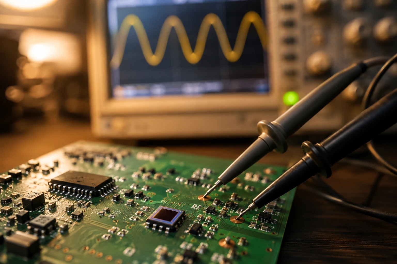
Está diseñando su OTDR (reflectómetro óptico en el dominio del tiempo) de última generación. Ya ha resuelto el problema de las fuentes láser, la modulación por ancho de pulso tiene buena pinta, pero ahora se enfrenta al extremo receptor. El detector.
Siempre es el mismo debate en el laboratorio de I+D, ¿verdad? ¿Intentamos abaratar costes con el silicio (Si) o apostamos por el arseniuro de indio y galio (InGaAs)?
Si echa un vistazo rápido a las hojas de datos, es posible que piense que tiene margen de maniobra. Pero aquí está la cruda realidad: si su equipo está orientado a las ventanas estándar de telecomunicaciones (1310 nm y 1550 nm), conseguir el fotodiodo equivocado no es sólo una diferencia de especificaciones menor, es la diferencia entre un instrumento de primer nivel y un pisapapeles.
En BeePhoton, Hemos visto a muchos ingenieros intentar “hackear” el sistema llevando los detectores a sus límites absolutos. A veces funciona. La mayoría de las veces, el resultado es un caos ruidoso. Hoy quiero explicarte las diferencias reales entre Fotodiodos de InGaAs frente a los de Silicio, específicamente para componentes de pruebas de fibra óptica. Nada de palabrería, solo la realidad de la ingeniería.
El campo de batalla de la longitud de onda: El límite de la física
Antes de hablar de precios o envases, hay que respetar la física. La diferencia fundamental entre estos dos materiales radica en su energía de banda prohibida. No se trata solo de teoría de libro de texto; dicta el límite superior de la longitud de onda que el detector OTDR puede ver realmente.
Silicio: El rey del corto alcance (850 nm)
El silicio es barato. Es abundante. Los procesos de fabricación están maduros porque toda la industria de semiconductores funciona con él.
El silicio tiene una energía de banda prohibida de aproximadamente 1,12 eV a temperatura ambiente. ¿Qué significa esto para nosotros? Significa que el Silicio es fantástico absorbiendo fotones en el rango visible y en el infrarrojo cercano (NIR) hasta unos 1000nm o 1100nm.
Si está construyendo un OTDR específicamente para pruebas de fibra multimodo (MMF) -principalmente LAN y centros de datos que funcionan a 850nm-El silicio es tu mejor amigo. Tiene un pico de respuesta en torno a los 900 nm.
Sin embargo, Sin embargo, una vez superados los 1100 nm, el silicio se vuelve transparente. Los fotones de un láser de 1310 nm atraviesan el material sin generar pares electrón-hueco. No hay corriente. No hay señal.
InGaAs: El estándar de las telecomunicaciones (1310nm/1550nm/1625nm)
Aquí es donde Fotodiodos PIN de InGaAs entrar en el chat. El arseniuro de indio y galio tiene una banda prohibida más pequeña (alrededor del 0,75 eV dependiendo de la relación de aleación). Esto le permite absorber fotones de menor energía, concretamente los que se encuentran en las bandas de la fibra monomodo (SMF).
Para un OTDR que mide redes de larga distancia, FTTx o PON, se trabaja con 1310nm, 1490nm, 1550nm y 1625nm. El silicio es inútil aquí. Si se quiere detectar algo, no queda más remedio que utilizar InGaAs.
Nota del ingeniero: Una vez vi a un competidor intentar comercializar una sonda “universal” que utilizaba un detector de Ge (Germanio) para ahorrar dinero respecto a los InGaAs. El germanio funciona en estas longitudes de onda, pero la corriente oscura (ruido) es significativamente mayor. Si te importa el rango dinámico (y en los OTDR, el rango dinámico lo es todo), el InGaAs es superior al Germanio.
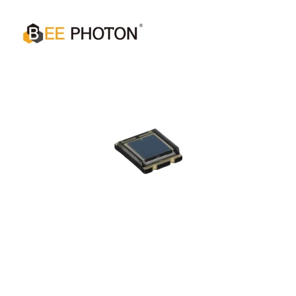
Fotodiodo PIN de Si con sensibilidad NIR mejorada (430-1100nm) PDCP08-201
En PDCP08-201 es un sistema de alto rendimiento Fotodiodo SMD Si PIN diseñado para la comunicación óptica de precisión y la detección médica[.1] Con una gran área activa de 2,9×2,9 mm, una sensibilidad NIR mejorada (0,70 A/W) y una corriente oscura ultrabaja (20 pA), este Fotodiodo SMD Si PIN garantiza una detección de señales y una fiabilidad superiores en un encapsulado compacto de montaje superficial.
Especificaciones técnicas clave: Sensibilidad y ruido
Pasemos a las matemáticas. No te preocupes, sé que los editores estándar de WordPress odian LaTeX, así que mantendré estas fórmulas limpias y fáciles de copiar y pegar.
Cuando seleccione un Detector OTDR, El equilibrio es doble: Cuánta señal puedo obtener (capacidad de respuesta) y cuánto ruido puedo tolerar (NEP/corriente oscura).
1. Capacidad de respuesta (R)
La capacidad de respuesta indica cuánta corriente eléctrica se obtiene para una potencia óptica determinada. La fórmula es la siguiente:
R = Ip / Popt
Dónde:
- R es la respuesta (amperios/vatio)
- Ip es la fotocorriente generada (Amperios)
- Popt es la potencia óptica incidente (vatios)
O relacionándolo con la eficiencia cuántica (QE):
R = (QE * q * lambda) / (h * c)
- lambda = longitud de onda
- q = carga del electrón
- h = Constante de Planck
- c = velocidad de la luz
Aquí está el truco:
- En 850nm, un buen detector de Silicio podría tener un R de 0,5 A/W.
- En 1550nm, un detector InGaAs de alta calidad de BeePhoton suele tener una R de 0,85 a 0,95 A/W.
Como el InGaAs es más eficiente en estas longitudes de onda más largas, su OTDR puede detectar reflexiones más débiles desde más abajo en la fibra. Esto se traduce directamente en una mayor distancia de medición.
2. Rango dinámico y corriente oscura
En un OTDR, se lanza un pulso fuerte y se escuchan los diminutos ecos de retrodispersión. Esto requiere un detector que se recupere rápidamente (baja capacitancia) y tenga un ruido de fondo muy bajo.
La corriente oscura (Id) es la corriente que fluye incluso cuando no incide luz en el detector. Es ruido.
Potencia equivalente de ruido (NEP) es una función de esta corriente oscura:
NEP = (sqrt(2 * q * Id)) / R
Si se utiliza un detector de baja calidad con una corriente oscura elevada, el “ruido de fondo” aumenta. La débil retrodispersión a 100 km de distancia queda sepultada por el ruido. Puedes promediar la señal todo lo que quieras, pero no puedes arreglar la mala física del hardware.
Fotodiodos PIN de InGaAs suelen ofrecer corrientes oscuras muy bajas (a menudo en el rango de nA o incluso pA para pequeñas áreas activas), lo que ayuda a conseguir ese rango dinámico de 40dB+ que todo el mundo desea.
Tabla comparativa: La chuleta
He elaborado esta tabla para que puedas ver las diferencias una al lado de la otra. Te resultará útil cuando tengas que justificar el coste de la lista de materiales ante tu jefe.
| Característica | Fotodiodo de silicio (Si) | Fotodiodo InGaAs |
|---|---|---|
| Longitudes de onda primarias | 400nm - 1100nm | 900nm - 1700nm |
| Lo mejor para | Luz visible, MMF (850 nm) | Telecomunicaciones, SMF (1310/1550 nm), SWIR |
| Respuesta (pico) | ~0,6 A/W @ 900nm | ~0,95 A/W @ 1550nm |
| Coste | Bajo | Moderado a alto |
| Corriente oscura | Muy bajo (rango pA) | Bajo (rango nA), depende del área activa |
| Velocidad (tiempo de subida) | Muy rápido | Rápido (apto para comunicaciones de alta velocidad) |
| Aplicación OTDR | Comprobadores de LAN de corto alcance | Metro, Largo recorrido, Probadores PON |
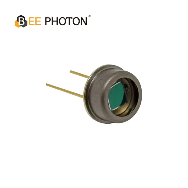
Fotodiodo PIN de Si con baja corriente oscura (350-1060nm) PDCT14-001
Mejore su equipo de medición óptica con nuestro fotodiodo PIN de Si con embalaje TO. Presenta una corriente oscura ultrabaja, alta consistencia y una ventana de borosilicato para una mayor durabilidad. Este fotodiodo PIN de Si de alto rendimiento está optimizado para aplicaciones exigentes.
Aplicación en el mundo real: Por qué es importante el área activa
Aquí hay algo que las hojas de datos no siempre te gritan: El tamaño del área activa.
En el diseño de OTDR, hay que hacer concesiones.
- Gran área activa (por ejemplo, 300um, 500um): más fácil acoplar la fibra al detector. No necesitas una mecánica de alineación de superprecisión.
- Área activa pequeña (por ejemplo, 75um, 30um): menor capacitancia.
¿Por qué importa la capacitancia? Ancho de banda.
Ancho de banda (BW) = 0,35 / tr
Dónde tr es el tiempo de subida. Una capacitancia alta (área grande) ralentiza el tiempo de subida.
Para un OTDR, la velocidad determina su Zona muerta. Si tu detector tarda en recuperarse tras la reflexión inicial de alta potencia del conector, puede que estés ciego durante los primeros 10 o 20 metros de la fibra. Esto es inaceptable para aplicaciones FTTH en las que el primer divisor está cerca.
En BeePhoton, A menudo recomendamos Fotodiodos PIN de InGaAs con áreas activas optimizadas que equilibran la eficiencia del acoplamiento con una baja capacitancia, lo que garantiza que su zona muerta de eventos sea lo más corta posible.
Estudio de un caso “secreto”: Cuando lo “barato” se volvió caro
Quiero compartir una historia (nombres cambiados, obviamente) sobre un cliente con el que trabajamos el año pasado. Llamémosles “OptiTest”.”
OptiTest estaba desarrollando un mini-OTDR portátil para el mercado FTTH. Para competir en precio, decidieron adquirir un detector de InGaAs de bajo coste a un proveedor de componentes genérico, ignorando las especificaciones de resistencia de derivación.
El problema:
Su prototipo funcionaba bien en el laboratorio con una bobina de 5 km. Pero cuando lo llevaron al terreno, la traza se volvió increíblemente “borrosa” a partir de los 20 km. Perdían unos 5 dB de rango dinámico en comparación con sus cálculos teóricos.
El diagnóstico:
Nos enviaron la unidad. Cambiamos su detector genérico por uno de nuestros fotodiodos InGaAs de alta resistencia. El problema no era la capacidad de respuesta, sino la ruido térmico generada por la baja resistencia de derivación del chip barato.
La solución:
Al cambiar a un detector BeePhoton, su potencia equivalente de ruido (NEP) disminuyó significativamente.
- Resultado: Recuperaron esos 5 dB de rango dinámico.
- Bonificación: El rastro era más limpio y requería menos tiempo de promediado. Esto significaba que el técnico podía terminar el trabajo en 10 segundos en lugar de 30 segundos. Sobre el terreno, el tiempo es oro.
Puede consultar nuestra gama aquí si quiere evitarse ese quebradero de cabeza: Categoría de fotodiodos PIN de InGaAs.
Integración del detector: No es sólo “Plug and Play”
Elegir el sensor es el primer paso. El segundo paso es el circuito.
Cuando se utilizan fotodiodos de InGaAs, es probable que se combinen con un amplificador de transimpedancia (TIA).
Vsalida = -Ip * Rf
- Rf es tu resistencia de realimentación.
Puedes tener la tentación de hacer Rf enorme para obtener una ganancia masiva (mucho voltaje para poca corriente). Pero hay que tener cuidado. Un gran Rf limita tu ancho de banda.
f_corte = 1 / (2 * pi * Rf * Cf)
- Véase es la capacitancia de realimentación.
Lo ideal es un detector de InGaAs empaquetado con un pigtail (fibra conectada) para minimizar la luz parásita y las pérdidas por inserción. Nosotros nos encargamos de la alineación en fábrica para que usted no tenga que juguetear con etapas XYZ en su línea de producción.
Por qué la experiencia es importante en la selección de componentes
Mira, cualquiera puede venderte un chip. Hay un millón de distribuidores en línea. Pero en BeePhoton, no nos limitamos a mover cajas. Entendemos el dolor de una traza ruidosa. Sabemos lo que ocurre cuando las fluctuaciones de temperatura cambian sus especificaciones de corriente oscura.
Llevamos años caracterizando componentes para pruebas de fibra óptica. No sólo nos fijamos en las especificaciones máximas, sino también en las mínimas, las desviaciones y la fiabilidad a lo largo del tiempo.
Cuando elige un socio para su cadena de suministro, necesita a alguien que pueda responderle: “¿Qué le ocurre a la linealidad de este detector si la potencia de entrada alcanza picos de +10dBm?”. (Spoiler: se satura, y podemos ayudarle a diseñar un circuito de protección).
Fotodiodo PIN de InGaAs de 800-1700nm PDIT03-231N
Nuestro diodo PIN de InGaAs para comunicación óptica está diseñado para redes de fibra óptica fiables. Este diodo empaquetado en TO proporciona una alta sensibilidad para sistemas de comunicación óptica, garantizando una excelente integridad de la señal.
PREGUNTAS FRECUENTES: Preguntas comunes sobre los detectores OTDR
P1: ¿Puedo utilizar un fotodiodo de avalancha (APD) en lugar de un fotodiodo PIN para OTDR?
A: Sí, y los OTDR de gama alta suelen hacerlo. Los APD tienen ganancia interna (M), lo que aumenta la sensibilidad. Sin embargo, requieren una tensión de polarización alta (a menudo 40 V-60 V) y son sensibles a la temperatura. Para los OTDR de mano o económicos, se suele preferir un fotodiodo PIN por su simplicidad y menor consumo de energía.
P2: ¿Afecta el embalaje del fotodiodo a la medición?
A: Absolutamente. Un estilo “Receptáculo” permite al usuario conectar un cable de conexión directamente al dispositivo, pero puede acumular polvo. Un estilo “Pigtailed” (fibra que sobresale) es mejor para el enrutamiento interno para evitar fugas de luz. Para los OTDR, solemos recomendar módulos en espiral empalmados al acoplador interno para conseguir la máxima estabilidad.
P3: ¿Por qué mi detector de InGaAs muestra un ruido elevado a altas temperaturas?
A: La corriente oscura en InGaAs se duplica aproximadamente cada 10 °C de aumento de temperatura. Si el OTDR se va a utilizar en el desierto o en una sala de servidores calurosa, es necesario tener en cuenta esta deriva o utilizar un detector refrigerado por TE (aunque es una exageración para la mayoría de las unidades portátiles). Un buen disipador de calor en la placa de circuito impreso es crucial.
P4: ¿Cuál es la diferencia entre InGaAs e InGaAs ampliado?
A: El InGaAs estándar se corta en torno a los 1700 nm. El InGaAs ampliado altera la composición del material para ver hasta 2600 nm. Para los OTDR estándar de telecomunicaciones (hasta 1625 nm o 1650 nm para monitorización activa), el InGaAs estándar es perfecto y más barato. Sólo se necesita extendido para la detección de gases o aplicaciones especiales.
Conclusión
Elegir entre Fotodiodos de InGaAs frente a los de Silicio en última instancia se reduce a tu longitud de onda.
- ¿Construyendo un comprobador LAN para 850nm? Ahorre dinero, utilice Silicio.
- ¿Está construyendo un OTDR serio para telecomunicaciones/FTTH (1310nm/1550nm)? Necesita InGaAs.
Pero más allá del material, preste atención al área activa, la capacitancia y la resistencia de derivación. Estas son las especificaciones ocultas que determinan si tu instrumento está “bien” o es “líder del mercado”.”
En BeePhoton, Estamos especializados en soluciones de detección de alto rendimiento. Ayudamos a los fabricantes a superar estas disyuntivas cada día.
¿Está listo para actualizar su detección óptica?
No dejes que un detector ruidoso arruine tus especificaciones de rango dinámico.
- ¿Necesita un presupuesto? Contacte con nosotros
- ¿Tiene alguna pregunta técnica? Envíenos un correo electrónico a info@photo-detector.com.
- Navega por la mercancía: Consulte nuestro Fotodiodo PIN de InGaAss página.
Construyamos juntos mejores instrumentos.