
Si usted es un ingeniero de I+D que diseña sensores ópticos de alta precisión, es probable que se haya enfrentado al clásico dilema de elegir la longitud de onda adecuada. Mientras que la longitud de onda estándar de 850 nm recibe la mayor parte de la atención de la industria, la especializada LED NIR de 855 nm está resolviendo discretamente algunos de los problemas más difíciles de alineación y filtrado en el escaneo de alta resolución, codificadores rotativos y barreras ópticas industriales.
A primera vista, una diferencia de 5 nm parece trivial. Después de todo, ¿qué son 5 nanómetros cuando se trata de una amplia curva espectral de infrarrojo cercano? Pero en el mundo de la optoelectrónica de alto rendimiento, ese pequeño desfase puede representar la diferencia entre un sensor que se sale de las especificaciones ante temperaturas cálidas y uno que funciona de forma fiable durante años.
Let’s dive into the core differences between a standard 850nm emitter and an LED NIR de 855 nm para que pueda tomar la mejor decisión para su próximo prototipo.
Descifrando los conceptos básicos: ¿Qué es un LED NIR de 855 nm?
En LED NIR de 855 nm es un diodo emisor de luz infrarroja cercana diseñado específicamente para emitir luz con una distribución espectral máxima centrada en los 855 nanómetros. La mayoría de estos diodos se fabrican utilizando materiales semiconductores de arseniuro de galio y aluminio (GaAlAs o AlGaAs). Al ajustar la proporción de aluminio con respecto al galio en las capas activas durante el proceso de crecimiento por deposición química de vapor metalorgánico (MOCVD), los ingenieros pueden ajustar con precisión la banda prohibida para alcanzar esta longitud de onda exacta.
En aplicaciones industriales B2B, a menudo recomendamos el LED NIR de 855 nm para tareas que requieren un control espacial estricto, haces altamente colimados o una coincidencia específica con filtros ópticos de paso de banda estrecho. Mientras que los LED estándar están diseñados para emitir la mayor potencia de luz bruta posible en un ángulo amplio, un componente premium LED NIR de 855 nm frecuentemente se diseña como un emisor de fuente puntual. Esto significa que la luz se limita a un área de emisión microscópica, lo que lo convierte en un excelente candidato para la colimación.
El duelo de nanómetros: LED IR de 850 nm frente a 855 nm
Al comparar una fuente estándar de 850 nm con una de LED NIR de 855 nm, estamos ante dos emisores que comparten la misma banda general de infrarrojo cercano (IR-A). Sin embargo, sus características de rendimiento en el mundo real difieren en áreas físicas y ópticas clave.
Física de semiconductores: Longitud de onda frente a Banda prohibida
Para entender por qué difieren estas dos longitudes de onda, debemos observar la banda prohibida del semiconductor. La longitud de onda máxima de un diodo emisor de luz es inversamente proporcional a la energía de la banda prohibida de la capa activa. Podemos expresar esto mediante una fórmula sencilla y universal:
Longitud de onda (lambda) = (h * c) / Eg
Para que esto sea práctico en la ingeniería óptica, podemos simplificarlo:
Longitud de onda (en nm) ≈ 1240 / Eg (en eV)
Si reorganizamos esto para hallar la energía de banda prohibida (Eg) de ambos emisores:
- Para un emisor estándar de 850 nm: Eg ≈ 1240 / 850 = 1,459 eV
- Para un LED NIR de 855 nm: Eg ≈ 1240 / 855 = 1,450 eV
Esta pequeña diferencia de 0,009 electronvoltios puede parecer microscópica, pero cambia el comportamiento del material bajo estrés térmico. Debido a que el LED NIR de 855 nm tiene una energía de banda prohibida ligeramente inferior, funciona de forma natural con una tensión directa (Vf) marginalmente menor para la misma corriente de accionamiento.
Potencia de salida frente a estabilidad de la longitud de onda de pico
Históricamente, los LED estándar de 850 nm han disfrutado de una enorme ventaja en potencia de salida óptica bruta. Debido a que 850 nm es la longitud de onda predeterminada para las cámaras de seguridad y los controles remotos de consumo, la escala de fabricación es enorme. Si solo se necesita inundar un área con luz infrarroja, los 850 nm resultan muy rentables.
Sin embargo, si su sensor depende de una longitud de onda de pico muy estable, un LED estándar de 850 nm puede ser un inconveniente. Los LED de 850 nm fabricados en serie suelen tener anchos de banda espectrales más amplios (medidos como ancho completo a la mitad del máximo, FWHM), que suelen oscilar entre 30 nm y 50 nm.
En LED NIR de 855 nm, especialmente cuando provienen de fabricantes especializados como BeePhoton, a menudo se clasifica y procesa para tener un ancho espectral más estrecho (a veces por debajo de 25 nm FWHM) y una emisión de pico altamente estable en condiciones de accionamiento por onda continua (CW).
LED NIR E850-180-201L4
En E850-180-201L4 es un sistema de alto rendimiento LED NIR de 850 nm diseñados para la detección industrial de precisión. Fabricado por Fotón abeja, este emisor de infrarrojos está diseñado para ofrecer una gran luminosidad y una estabilidad excepcional, lo que lo convierte en la fuente de luz ideal para entornos de automatización exigentes.
Fuente puntual frente a emisor de superficie: por qué el LED NIR de 855 nm gana en sensores ópticos de precisión
El mayor diferenciador entre un LED genérico de 850 nm y uno de precisión LED NIR de 855 nm suele ser la estructura interna del propio chip.
Standard 850nm LEDs are typically “surface emitters.” The entire top surface of the semiconductor die glows, but this glow is interrupted by the wire bond pad in the middle of the chip. This creates a messy emission profile with a dark spot right where your optical system expects the brightest light. For security illumination, this does not matter. For a sub-micron optical encoder, it is a problem.
Aquí es donde la especializada LED NIR de 855 nm fuente puntual entra en escena.
En un emisor de superficie estándar (típico de 850 nm), se coloca una almohadilla de conexión de cables justo en el medio de la región de emisión activa, lo que provoca un punto oscuro notable en el centro del haz de salida y genera un patrón de luz difuso.
En un emisor de fuente puntual (típico de 855 nm), se deposita una capa de enmascaramiento sobre la estructura del semiconductor, con una microapertura que restringe la emisión de luz a una ventana circular diminuta y uniforme (p. ej., de 50 a 150 micrómetros). La conexión del cable se realiza en la capa de enmascaramiento fuera de la apertura, lo que significa que no hay sombra del cable y el haz es increíblemente uniforme.
Eliminación del efecto de penumbra en codificadores rotativos
Si está diseñando un codificador óptico lineal o rotativo de alta resolución, su emisor necesita proyectar la sombra de una rejilla móvil sobre una matriz de fotodiodos. Si su fuente de luz tiene un área de emisión grande, creará un borde de sombra difuso conocido como penumbra.
The width of this fuzzy edge (P) is determined by the emitter’s aperture diameter (d), the distance from the emitter to the grating (g), and the distance from the grating to the detector (D):
P = d * (D / g)
If you use a standard 850nm surface emitter with an effective chip diameter of 300 micrometers, your penumbra will be relatively wide, causing phase errors and limiting your encoder’s resolution.
Si cambia eso por una LED NIR de 855 nm fuente puntual con una apertura de 50 micrómetros, ¡la penumbra se reduce por un factor de seis! Las sombras resultantes son nítidas, lo que le permite leer pasos de rejilla mucho más finos sin degradación de la señal.
Gestión de los cambios de temperatura en un LED NIR de 855 nm
Al operar un sensor en un entorno industrial, la temperatura es su enemigo constante. Todos los emisores infrarrojos basados en AlGaAs sufren un fenómeno físico conocido como desplazamiento al rojo térmico: a medida que aumenta la temperatura de la unión, la banda prohibida se reduce y la longitud de onda de emisión máxima se desplaza hacia una longitud de onda más larga.
Para la mayoría de los diodos de infrarrojo cercano, este coeficiente de temperatura (alfa_T) es relativamente constante:
alfa_T ≈ 0,25 nm/°C a 0,30 nm/°C
Las matemáticas detrás del desplazamiento al rojo inducido por la temperatura
Let’s look at how this thermal shift affects an LED NIR de 855 nm bajo condiciones de funcionamiento típicas. Podemos calcular la longitud de onda máxima de funcionamiento utilizando esta aproximación lineal:
lambda(T) = lambda_0 + alpha_T * (T_junction – T_0)
Dónde:
- lambda(T) es la longitud de onda máxima a la temperatura de funcionamiento.
- lambda_0 es la longitud de onda máxima a temperatura ambiente (normalmente 855 nm a 25 °C).
- alfa_T es el coeficiente de desplazamiento térmico (usaremos 0,26 nm/°C).
- T_unión es la temperatura real de la unión del semiconductor.
- T_0 es la temperatura de referencia (25 °C).
Para hallar la temperatura de la unión (T_unión), debemos calcular el aumento térmico causado por la corriente de accionamiento:
T_unión = T_ambiente + (Potencia_disipada * R_térmica)
Let’s plug in some realistic numbers for a high-quality LED NIR de 855 nm encapsulado en una lata metálica TO-46:
- Temperatura ambiente (T_ambiente) = 55 °C (dentro de una carcasa de sensor industrial sellada).
- Corriente directa (If) = 80 mA.
- Voltaje directo típico (Vf) = 1.6 V.
- Resistencia térmica del encapsulado (R_térmica) = 150°C/W.
Primero, calcule la disipación de potencia:
Potencia_disipada = Vf * If
Potencia_disipada = 1.6 V * 0.08 A = 0.128 W
Ahora, calcule la temperatura de la unión:
T_unión = 55°C + (0.128 W * 150°C/W)
T_unión = 55°C + 19.2°C = 74.2°C
Finalmente, calcule la longitud de onda de pico desplazada:
lambda(T) = 855 nm + 0.26 nm/°C * (74.2°C – 25°C)
lambda(T) = 855 nm + 0.26 nm/°C * (49.2°C)
lambda(T) = 855 nm + 12.8 nm ≈ 867.8 nm
A una temperatura de funcionamiento interna de 74.2°C, nuestro LED NIR de 855 nm está alcanzando en realidad un pico de casi 868 nm!
Por qué esto es importante para los filtros de paso de banda estrecho
In many outdoor or high-ambient-light industrial environments, your sensor’s receiver needs to ignore sunlight and overhead factory lighting. To do this, engineers place an optical bandpass filter in front of the photodiode.
Si diseña su receptor con un filtro de paso de banda muy estrecho centrado exactamente en 850 nm con un ancho de banda de 10 nm (lo que significa que solo permite el paso de luz de 845 nm a 855 nm), un LED estándar de 850 nm que funcione a alta temperatura se desviará rápidamente fuera de la banda de paso.
For instance, at room temperature, a standard 850nm LED fits perfectly within the 845nm to 855nm transmission window. However, when operating in high ambient heat, the peak wavelength of that standard emitter redshifts to 861nm, which falls entirely outside the filter’s passband, causing a massive loss of optical signal.
Al comprender esta desviación, puede tomar una decisión informada. Algunos ingenieros utilizan específicamente un LED NIR de 855 nm paired with an 860nm or 865nm bandpass filter. This ensures that as the system warms up to its stable operating temperature, the emitter’s peak wavelength drifts directly into the sweet spot of the filter’s transmission curve, rather than drifting out of it.
Diodo IR de haz estrecho: ¿Se puede colimar fácilmente el LED NIR de 855 nm?
Sí, un diodo IR de haz estrecho basado en un LED NIR de 855 nm es mucho más fácil de colimar que los emisores estándar de gran angular. Debido a que el diseño de fuente puntual concentra la emisión de luz en un área física diminuta, puede colocar una lente de colimación muy cerca del chip.
Esto le permite proyectar un haz paralelo y estrecho a largas distancias con una divergencia de haz mínima (a menudo inferior a un semiángulo de 5 grados). Si está construyendo cortinas de luz ópticas, sensores de detección de bordes o escáneres reflectantes, este haz estrecho evita la diafonía óptica y garantiza que solo el objeto objetivo interrumpa la trayectoria de la luz.

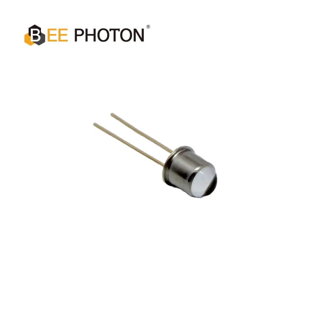
LED NIR E850-25-001-L20
El E850-25-001-L20 es un equipo de alto rendimiento LED NIR de 855 nm diseñado para aplicaciones industriales exigentes. Fabricado por Bee Photon, este emisor de infrarrojos presenta un estrecho ángulo de emisión de 20 grados, que proporciona una alta intensidad radiante de 25 mW/sr adaptada a la detección de precisión. Su robusto diseño garantiza una alta fiabilidad y un rendimiento constante en un amplio rango de temperaturas de funcionamiento.
Comparación directa: LED estándar de 850 nm frente a LED NIR de 855 nm
To simplify your selection process, let’s look at how a standard, mass-produced 850nm surface-emitting LED stacks up against a precision-grade LED NIR de 855 nm fuente puntual bajo restricciones de ingeniería típicas.
| Parámetro de ingeniería | LED de superficie estándar de 850 nm | Fuente puntual de LED NIR de 855 nm |
|---|---|---|
| Área típica del emisor | Cuadrado grande (aprox. 300 x 300 um) | Círculo microscópico (50 a 150 um de diámetro) |
| Uniformidad del perfil del haz | Moderada (sombreada por la conexión de cable central) | Excelente (uniforme, sin sombras de cables) |
| Potencia de salida óptica bruta | Muy alta (debido a la gran área activa) | Moderada (restringida por la microapertura) |
| Facilidad de colimación | Difícil (conduce a una divergencia amplia/bordes difusos) | Muy fácil (permite un diodo IR de haz estrecho y ajustado) |
| Ancho espectral (FWHM) | Amplio (típico de 30 nm a 50 nm) | Estrecho (típico de 15 nm a 25 nm) |
| Encapsulado Típico | SMD de plástico o epoxi radial moldeado | Cápsulas metálicas herméticas TO-18 / TO-46, SMD cerámico |
| Casos de Uso B2B Principales | Cámaras de seguridad, iluminación IR general | Encóderes rotativos, escáneres ópticos, sensores de borde |
| Coste Unitario Relativo | Bajo (precios de mercado masivo) | Medio a alto (especializado, baja tolerancia) |
Escenarios de Ingeniería del Mundo Real: Cuándo Implementar un LED NIR de 855 nm
Let’s look at a couple of anonymous, real-world case studies based on actual industrial designs to see how choosing an LED NIR de 855 nm resolvió problemas críticos de campo.
Estudio de Caso 1: Resolución del jitter de fase en encóderes de articulaciones robóticas
Una empresa de automatización industrial estaba diseñando un encóder rotativo absoluto de alta resolución para un brazo robótico multieje. El prototipo utilizaba un LED SMD de emisión superficial estándar de 850 nm para proyectar luz a través de un disco encóder de cromo sobre vidrio.
Durante las pruebas de ciclo térmico, el equipo de ingeniería notó un jitter de fase significativo y errores angulares a temperaturas superiores a 50 °C.
Tras una inspección más detallada, se dieron cuenta de que el amplio perfil de emisión y la sombra del cable de conexión central del LED de 850 nm estaban provocando que el patrón de luz se deformara ligeramente a medida que el LED se expandía térmicamente. Esta deformación estructural se tradujo directamente en errores de lectura en la matriz de detectores.
Los ingenieros sustituyeron el emisor de superficie por una LED NIR de 855 nm fuente puntual con una apertura de emisión de 100 micrómetros. Debido a que la fuente puntual carece de la sombra del cable de conexión central y tiene un haz altamente simétrico, produjo transiciones de sombra increíblemente nítidas en el receptor de fotodiodo.
El jitter de fase se eliminó por completo y el encóder mantuvo su precisión de sub-arcosegundo en todo el rango operativo de -40 °C a 85 °C.
Estudio de Caso 2: Diseño de una barrera de haz óptico para exteriores
Una empresa de seguridad exterior estaba construyendo una barrera de haz infrarrojo activo para proteger perímetros de alta seguridad. El sistema utilizaba un transmisor y un receptor situados a 50 metros de distancia.
Para evitar falsas alarmas provocadas por el sol, el receptor utilizó un filtro óptico de paso de banda de 850 nm muy estrecho con un ancho de banda de 8 nm.
En las primeras pruebas de campo, el sistema funcionó perfectamente por la mañana, pero perdía la conexión con frecuencia durante el calor de la tarde.
The problem was thermal redshift. Under direct midday sunlight, the transmitter’s internal temperature reached 65°C, causing the standard 850nm LED to drift to 861nm—completely outside the 846nm to 854nm passband of the filter.
Para solucionar esto, el equipo de diseño cambió a un especializado LED NIR de 855 nm combinado con un filtro de paso de banda de 860 nm.
Porque el LED NIR de 855 nm comienza naturalmente en una longitud de onda ligeramente más larga, su desplazamiento al rojo por la tarde (con un pico alrededor de los 864 nm) se alineó con las tolerancias térmicas más amplias de la nueva configuración del filtro de 860 nm. Este pequeño ajuste restauró el margen de la señal, manteniendo la barrera de haz operativa incluso bajo el sol abrasador del mediodía.
Eligiendo al compañero adecuado: Fotodiodos y fuentes de luz
Seleccionar su LED NIR de 855 nm es solo la mitad de la batalla; también debe emparejarlo con un receptor que coincida con sus características ópticas. Los fotodiodos de silicio estándar y los fotodetectores PIN presentan una responsividad espectral máxima entre 800 nm y 950 nm, lo que los hace intrínsecamente compatibles con las longitudes de onda de 850 nm y 855 nm.
Sin embargo, para el escaneo óptico de alta velocidad o alta precisión, debe buscar fotodetectores que ofrezcan filtros integrados de bloqueo de luz diurna o recubrimientos antirreflectantes (AR) personalizados optimizados para la ventana de 850-860 nm. Si su sensor funciona en entornos de alta frecuencia (como comunicaciones ópticas en el rango de los gigahercios o detección de distancia por tiempo de vuelo), asegurarse de que tanto su LED NIR de 855 nm como su fotodetector coincidan físicamente evita la atenuación de la señal y mantiene los tiempos de subida/bajada extremadamente nítidos.
Si está adquiriendo componentes, le recomendamos explorar fuentes de luz infrarroja de alto rendimiento para encontrar emisores con formas de haz altamente controladas y una distorsión espacial mínima.

Matriz de fotodiodos PIN de Si PDCA02-602
La serie Bee Photon PDCA se ha diseñado específicamente como un Fotodiodo de supresión de fondo para resolver complejos retos de detección en entornos industriales. Al utilizar una arquitectura de dos segmentos de alta precisión (PD A y PD B), este dispositivo permite el procesamiento diferencial de señales, filtrando eficazmente las interferencias de fondo. Es la principal elección para los fabricantes que diseñan interruptores ópticos y sensores de proximidad con supresión de fondo fiables.
Preguntas frecuentes: Respuestas rápidas para ingenieros de diseño óptico
¿Es visible para el ojo humano un LED NIR de 855 nm?
Not for practical illumination purposes, but yes, you can see a very faint red glow if you look directly at the emitter in a completely dark room. This occurs because the wide tail of the LED’s spectral emission curve slightly bleeds into the extreme edge of human vision (which ends around 780nm). An LED NIR de 855 nm tendrá un resplandor rojo ligeramente menos visible que un LED estándar de 850 nm, pero no es completamente encubierto como un emisor de 940 nm.
¿Puedo sustituir directamente un LED de 850 nm por un LED NIR de 855 nm?
En la mayoría de los casos, sí, los parámetros eléctricos son casi idénticos. La tensión directa de un LED NIR de 855 nm is typically around 1.5V to 1.7V, which matches standard 850nm drivers. However, if your system uses a very narrow optical filter, you must verify that the 5nm shift does not push your emitter’s output outside the filter’s transmission band.
¿Qué diferencia a un LED NIR de 855 nm de un diodo láser?
Un diodo láser emite luz coherente y altamente monocromática con un ancho espectral (FWHM) de menos de 1 nm. Un LED NIR de 855 nm emite luz incoherente en un ancho espectral más amplio (normalmente de 15 nm a 30 nm). Los LED son mucho menos sensibles a las descargas electrostáticas (ESD), tienen una vida útil más larga, no requieren certificaciones de seguridad complejas y son significativamente más rentables para los sensores industriales B2B.
¿Dónde puedo comprar un LED NIR de 855 nm de alta calidad?
Si está adquiriendo un LED NIR de 855 nm para un producto industrial de precisión, debe asociarse con un fabricante especializado en optoelectrónica. Los distribuidores de catálogo estándar suelen ofrecer LED de iluminación genéricos, pero las fuentes puntuales de alta precisión requieren una clasificación y pruebas especializadas.
Puede encontrar una amplia gama de fuentes de luz de grado industrial confiables y fotodetectores compatibles directamente a través de BeePhoton.
Lograr su diseño óptico correctamente a la primera
Elegir entre 850 nm y 855 nm no es solo cuestión de elegir un número en una hoja de datos. Se trata de comprender cómo maneja su sistema la deriva térmica, el ruido óptico y la colimación de la luz. Si está construyendo una cámara de seguridad simple, el estándar de 850 nm suele ser suficiente. Pero si está construyendo un codificador, un sistema de alineación de telémetro láser o un sensor médico de alta precisión, utilizar una LED NIR de 855 nm fuente puntual le ahorrará innumerables horas de resolución de problemas en el futuro.
En BeePhoton, ayudamos a los equipos de I+D a diseñar, prototipar y fabricar configuraciones de sensores ópticos personalizados. Ya sea que necesite ayuda para seleccionar un emisor de haz estrecho, emparejar un fotodiodo con su longitud de onda específica o adquirir componentes de alta confiabilidad fuentes de luz infrarroja de alto rendimiento, nuestro equipo de ingeniería está aquí para ayudar.
¿Tiene un diseño óptico complejo en su mesa de trabajo?
Póngase en contacto directo con nosotros a través de nuestro página de contacto o envíe un correo electrónico a nuestro departamento de ingeniería a info@photo-detector.com con las especificaciones de su proyecto. Podemos asistirle con embalaje personalizado, clasificación especializada por longitud de onda y prototipado rápido para ayudarle a comercializar su sensor con total confianza.


