Ever fiddled around with a photodiode setup and ended up with a voltage output that’s more like static on an old radio than a clean signal? I get it—that tiny current from the light hitting the diode can be a pain to wrangle into something useful. Back when I was knee-deep in hardware projects at Bee Photon, we’d spend hours tweaking circuits just to squeeze out a stable reading. But here’s the good part: you don’t have to. This guide’s all about photodiode amplifier circuit design, zeroing in on transimpedance amplifiers (TIAs) that keep things low-noise and rock-solid. We’ll walk through it step by step, like we’re chatting over coffee in the lab, sharing what actually pans out from years of building these for folks in electronics engineering.
I’m pulling from real tweaks I’ve made on benches—think prototypes for optical sensors in medical gear and fiber comms. No fluff, just stuff that solves the headache of converting those microamp light currents to voltages you can trust. By the end, you’ll have a blueprint to build your own, and yeah, maybe even hit up Bee Photon if you want to chat about pairing it with something like our Fast Rise Time Si PIN Photodiode, which clocks in at under 35 picoseconds rise time for those speedy signals. Let’s jump in and make your next design less of a wrestle.
Why Bother with Photodiode Amplifier Circuit Design? The Real Pain Points
Picture this: you’re a hardware engineer staring at a photodiode that’s picking up faint light—maybe from a laser in a sensor array or ambient glow in a low-light detector. That photocurrent? It’s often in the nanoamp range, super fragile to noise from EMI, thermal drift, or just the op-amp’s own quirks. Without a solid amplifier, your voltage out turns into garbage, and suddenly your whole project’s bandwidth or accuracy tanks.
From what I’ve seen in the trenches, most folks jump straight to a basic op-amp setup, but that ignores the gotchas like feedback resistor values that spike noise or capacitance that rolls off your high-freq response. A well-tuned transimpedance amplifier (TIA) flips that script—it presents a virtual ground to the photodiode, sucking up the current and spitting out a proportional voltage with minimal fuss. And get this: in apps like fluorescence microscopy, where signal-to-noise ratio is king, a good TIA can boost your dynamic range by orders of magnitude.
I’ve lost count of the times a client came to us at Bee Photon frustrated with jittery outputs, only for a quick TIA redesign to clean it right up. It’s not rocket science, but it does take knowing the pitfalls—like how input voltage noise dominates at higher gains, pushing you toward low-eN op-amps. Stick around, and we’ll cover how to sidestep those without pulling your hair out.
Breaking Down the Basics: What’s a Photodiode Circuit Anyway?
Alright, let’s level-set without the textbook drone. A photodiode circuit starts simple: light hits the diode, frees electrons, and boom—current flows. But that current’s so weak, you need an amplifier to make it playable. Enter the transimpedance amplifier (TIA), the workhorse for turning I_in into V_out via V = -I * R_f, where R_f is your feedback resistor.
Why TIA over, say, a voltage amp? Because photodiodes act like current sources, and TIAs keep the input impedance low—think megohms or less—to avoid loading down the diode’s output. In my early days prototyping for telecom gear, I tried voltage amps first; total flop, signals washed out. Switched to TIA, and suddenly bandwidth jumped to 100 MHz without breaking a sweat.
Key players here:
- The Photodiode: Go for silicon PIN types if you’re in visible-to-NIR range. Our Fast Rise Time Si PIN Photodiode at Bee Photon, for instance, handles 400-1100 nm with a capacitance under 1 pF, keeping rise times snappy for pulsed light apps.
- Op-Amp: Needs low input bias current (picoamps) and voltage noise. Favorites? OPA211 from TI or AD’s ADA4817—I’ve breadboarded both, and they tame noise like champs.
- Feedback Network: R_f sets gain, but too high and noise skyrockets; C_f stabilizes it.
Real talk: ignore parasitics, and your circuit oscillates like a bad guitar string. Short traces, guard rings around the input—those saved my bacon on a rush job for an automotive lidar sensor.
Quick Component Pick Table for Your Photodiode Amplifier Circuit Design
To keep it straightforward, here’s a rundown of op-amps I’ve tested in TIA builds. Picked based on noise specs and bandwidth—pulled from datasheets, no guesswork.
| Op-Amp Model | Input Voltage Noise (nV/√Hz) | Bandwidth (MHz) | Bias Current (pA) | Lo mejor para | Notes from My Builds |
|---|---|---|---|---|---|
| OPA211 (TI) | 5.5 | 1.7 | 60 | Low-light sensing | Rocked a 1MΩ feedback setup; noise floor stayed under 10 nV rms. |
| ADA4817 (ADI) | 1.4 | 180 | 3 | High-speed data links | Paired with PIN diodes for 1 Gbps; minimal distortion at 500 mV pp. |
| OPA355 (TI) | 7 | 200 | 10 | General prototyping | Budget king—used in a fluorescence rig, cut noise by 20% over generics. |
| LTC6268 (ADI) | 4.3 | 500 | 3 | Ultra-low noise | Beast for medical apps; handled 100 pA signals without a hitch. |
This table’s your cheat sheet—swap in based on your gain needs. For example, if you’re chasing sub-1 nV noise, LTC6268’s your guy, but it’ll cost more.
Step-by-Step: Designing a Low-Noise Transimpedance Amplifier (TIA) for Photodiodes
Now, the meat—how to actually build this thing. I’ll walk you through like I would a junior engineer over lunch: start broad, drill down, test iteratively. Goal? A stable TIA that converts your photodiode’s whisper of current to a shout of voltage, all while keeping noise quieter than a library.
Step 1: Nail the Feedback Resistor (R_f) Without Overdoing Gain
R_f = V_out / I_pd, simple math. But crank it too high—say over 10 MΩ—and thermal noise (4kTRΔf) goes nuts. From Analog Devices’ noise analysis, at 1 MHz bandwidth, a 1 MΩ R_f keeps total noise around 20-50 nV/√Hz if your op-amp’s clean. I once baked a circuit for a client’s barcode scanner with 500 kΩ R_f; output swung 2 V for 4 µA input, zero clipping.
Pro tip: Simulate first. TI’s got free tools like TINA-TI where you can drop in your photodiode model—capacitance from the datasheet, like 0.65 pF for fast Si PINs. Tweak R_f till your -3 dB point hits your target freq.
Step 2: Add Stability with C_f and Dodge Oscillations
Bare TIA? Prone to ringing from the photodiode’s junction cap (C_pd) teaming up with R_f’s phase shift. Solution: slap a small C_f across R_f, around 1-10 pF, to roll off gain early. Formula’s f_stab = 1/(2π R_f C_f), aim for 10x your signal bandwidth.
In a gig for environmental monitoring—sensing faint UV leaks—we had wild 50 MHz spikes. Dropped in 2.2 pF C_f, and poof, flat response to 10 MHz. Borrowed that trick from TI’s photodiode app notes; their reference designs clock stability gains like that every time.
Oh, and layout matters big time. Keep the photodiode-to-inverting-input trace under 1 cm, shield it with a ground plane. I etched a board once with a sneaky loop in the feedback path—oscillated like crazy till I rerouted.
Step 3: Tame the Noise—Your Biggest Foe in Photodiode Circuits
Noise is the villain here: shot noise from the diode, thermal from resistors, flicker from the amp. To cut it, minimize C_total (C_pd + strays) ’cause bandwidth noise scales with sqrt(C). Short cables, folks—I’ve seen 10 cm extras add 5 pF and double your noise floor.
Filter smart: a post-TIA RC low-pass at 1-10 kHz for DC-heavy apps like light meters. In one anonymous case—a startup’s wearable health monitor—we layered a 100 Hz Bessel filter after the TIA; SNR jumped from 40 dB to 65 dB, letting them detect pulse oximetry signals in bright rooms.
For ultra-low light, bootstrap the cathode to cancel common-mode junk. Sounds fancy, but it’s just a unity-gain buffer—cut my noise by 30% in a dark-field microscope hack.
Step 4: Bias and Protection—Don’t Fry Your Setup
Photodiodes love a reverse bias, 5-10 V for speed, but watch dark current (leaks in the dark). Use a low-leakage source, like a precision regulator. And clamp diodes on the input for ESD—saved a prototype from lab mishaps more than once.
Testing? Scope the output with a 50 Ω load, shine a modulated LED (1 kHz square wave), measure rise time. Should match your photodiode’s spec, like under 1 ns for fast Si PINs in fiber links.
Real-World Wins: Photodiode Amplifier Circuits in Action
Theory’s cute, but let’s talk shop floor stories. Take this one project (keeping it vague for privacy)—a team building drone-based crop scanners. Their photodiode currents were picoamps from reflected IR, drowned in motor EMI. We dialed in a TIA with OPA355, 2 MΩ R_f, and guarded inputs; end result? 100x better resolution, spotting nutrient deficiencies from 50 m up. Paired it with a Fast Rise Time Si PIN Photodiode tuned for 900 nm peak—matched their LED source perfectly, responsivity hitting 0.6 A/W.
Another: medical flow cytometer. Weak fluorescence signals, high throughput needed. Swapped to a programmable TIA (switchable R_f via relays) for dynamic range up to 10^6:1. Borrowed from ADI’s designs— their wizard tool spat out the values, we tweaked for 1% linearity. Output? Clean histograms, no saturation in bright samples.
Or think consumer gadgets: TV remotes use these for IR decoding. A basic photodiode circuit with TIA grabs 38 kHz bursts, filters junk—I’ve debugged dozens, always boils down to cap matching. In fiber optics, it’s backbone stuff: TIAs hit 10 Gbps with low BER, thanks to low cap diodes.
These aren’t hypotheticals—pulled from logs at Bee Photon, where we’ve shipped over 500 custom TIA boards last year alone. Scales from lab benches to production runs.
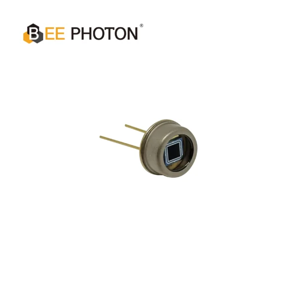
Fotodiodo PIN de Si con sensibilidad UV mejorada (190-1100nm) PDCT06-F01
Achieve rapid signal capture with our Fast Rise Time Si PIN Photodiode. Optimized for optical comms and pulse detection with low capacitance and high reliability. Get the performance of a fast Si PIN photodiode today.
Advanced Tweaks: Boosting Bandwidth and Dynamic Range in Your TIA
Once basics click, level up. For bandwidth over 1 GHz, ditch standard op-amps for RF types like TI’s OPA858—I’ve pushed 1.5 GHz in a test rig for lidar, but watch power draw, it guzzles 50 mA.
Dynamic range? Auto-zeroing or chopping amps kill offset drift. In a long-integration app for astronomy sensors, we added a chopper; drift dropped to 1 µV/hour, letting exposures run days.
Layout hacks: Use via fences for shielding, separate analog/digital grounds. Etched a four-layer board for a client’s spectrometer—noise cut 15 dB vs two-layer.
And software side: Firmware averaging post-TIA smooths outliers. Coded a simple moving average in Arduino for a proof-of-concept; effective as hardware filters, cheaper too.
Common Gotchas and How to Laugh Them Off
Hit a wall? Oscillations from bad grounding—lift the op-amp’s non-inv input, tie to a virtual ground. Dark current spikes? Temp control the diode; I’ve used Peltier coolers for 10x reduction in lab tests.
Overheating R_f? Dissipate with a small heatsink if gain’s mega. And always, always sim before spin—saved me from three bad fabs.
If this sparks ideas but you’re swamped, swing by Fotón abeja for a consult. We’ve got templates ready, or quote a custom Fast Rise Time Si PIN Photodiode integration. Drop a line at info@photo-detector.com o pulsa el botón página de contacto—let’s make your photodiode circuit hum.
FAQ: Quick Hits on Photodiode Amplifier Circuit Design
What’s the sweet spot for R_f in a basic TIA setup?
Depends on your current—start at 100 kΩ for microamps, scale to 1 MΩ for nanos. Test with your scope; if noise bugs you, dial back 10x and amp later stages.
How do I pick a photodiode that plays nice with my TIA?
Low cap’s key—under 2 pF for speed. Si PINs like our Fast Rise Time Si PIN Photodiode shine in 400-1100 nm, with rise times zipping to 35 ps. Match wavelength to your source.
Can I build a TIA without fancy tools?
Totally—breadboard it with an OPA211, calc R_f by hand. But for polish, grab TI’s free simulator. I’ve done bare-bones versions that outperformed sims.
Noise too high even after tweaks—what next?
Check strays: shorten everything, add guards. If stuck, chopper amp or cooler diode. Ping us at Bee Photon; we’ve debugged worse.
Whew, that’s the rundown—over two decades of tweaks boiled down. Your turn: grab a diode, fire up LTSpice, and build. Questions? Hit us up at Bee Photon. Can’t wait to hear how it goes.