If you’ve ever wondered what makes those TV remotes work so reliably, it’s all about infrared light bouncing around invisibly. Most folks don’t think much about it until something goes wrong, like the remote acting up in bright sunlight. That’s where 940nm phototransistors come in – they’re the unsung heroes in many remote control receivers.
I’ve tinkered with these components for years at Bee Photon, building custom setups for everything from home theater gear to simple appliance controls. Today, I’ll walk you through designing solid IR remote control circuits using these 940nm IR sensors. We’ll keep it practical, no fluff, just stuff that actually works in real projects.
Why 940nm? The Sweet Spot for IR Remotes
You might ask why not some other wavelength. Well, 940nm has been the go-to for consumer IR remotes pretty much forever. It’s the standard because it balances range, reliability, and cost perfectly.
Most TV remotes and air conditioner controls use IR LEDs that peak around 940nm. The receivers are tuned to match, so pairing a 940nm phototransistor with a standard emitter gives you great performance without fighting ambient light too much.
Sunlight and incandescent bulbs throw out IR too, but at 940nm, it’s easier to filter out the noise. That’s why you’ll see black-tinted lenses on these sensors – they block visible light while letting the good stuff through.
In the consumer electronics world, IR remotes are still huge. Even with all the smart home Wi-Fi stuff, basic remotes rely on IR for simple, low-power control. We’ve supplied silicon phototransistors tuned to 940nm for tons of these applications, and they just keep working year after year.
Basics of How IR Remote Systems Work
Let’s break it down simply. An IR remote system has two main parts:
- The transmitter (your remote): An IR LED pulses light at around 38kHz, modulated with data codes.
- The receiver: A sensor like a 940nm phototransistor or integrated module picks up those pulses and turns them into electrical signals.
The magic happens with modulation. Without it, ambient IR would swamp the signal. By pulsing at 38kHz (the most common carrier), the receiver can ignore steady light sources.
Common protocols? NEC is everywhere in Asian-made gear, RC-5 in older European stuff. Both work fine with 940nm setups.

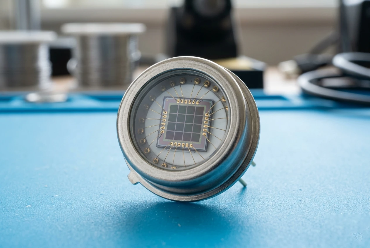
Si phototransistor PTCP Series PTCP001-102
High-sensitivity Silicon Phototransistor designed for precision detection in the 800-1100nm spectral range. This black plastic IR sensor ensures minimal noise and high reliability. Ideal for industrial applications requiring a robust silicon phototransistor with excellent response speed.
Phototransistor vs. Integrated Receiver Modules
Here’s where choices get interesting. You can go discrete with a plain 940nm phototransistor, or use an all-in-one module like TSOP series.
| Aspect | Discrete 940nm Phototransistor | Integrated IR Receiver (e.g., TSOP38338) |
|---|---|---|
| Cost | Cheaper, basic parts | A bit more, but still affordable |
| Complexity | Need extra amps, filters, demodulation | Built-in amp, filter, demodulator |
| Noise Rejection | Okay, but sensitive to ambient light | Excellent, tuned to 38kHz |
| Flexibility | Great for custom frequencies or DC detection | Locked to specific carrier (usually 38kHz) |
| Speed | Slower rise/fall times (5-10µs typical) | Faster, optimized for remotes |
| Power Use | Low | Very low |
For most consumer remote apps, integrated modules win hands down. But if you’re building something custom – like a proximity sensor or non-standard protocol – a discrete silicon phototransistor gives you more control.
At Bee Photon, we often recommend starting with our Silicon Phototransistor for prototypes where you need that flexibility.
Building a Basic IR Remote Control Circuit
Okay, let’s get hands-on. Here’s a simple IR remote control circuit using a discrete 940nm IR sensor.
You’ll need:
- 940nm phototransistor (like our silicon ones)
- Resistors: 10k pull-up, 100Ω for LED indicator
- Transistor for amplification (2N2222 or similar)
- Capacitors for filtering
- Microcontroller if decoding full codes (or just a flip-flop for on/off)
The phototransistor acts like a switch – light hits it, current flows from collector to emitter.
Basic receiver setup:
- Connect collector to VCC via pull-up resistor.
- Emitter to ground.
- Output from collector – goes low when IR detected.
For a full remote control receiver, add a 38kHz bandpass filter or use an op-amp comparator.
One project I worked on was for a custom media player. We used a 940nm phototransistor with a simple amp stage, then fed it to an Arduino for NEC decoding. Worked flawlessly up to 8 meters, even in a sunny room.
Simple Discrete Receiver Example
Here’s a rough schematic idea (text version):
- Phototransistor collector → 10k resistor → +5V
- Collector → base of NPN transistor
- Emitter of phototransistor → GND
- NPN emitter → GND
- NPN collector → relay or LED → +5V
When IR hits, phototransistor conducts, turns on the NPN, activates your load.
For better range, add a transimpedance amp:
Use an op-amp (LM358) with feedback resistor. Converts current to voltage nicely.
Key Design Tips for Reliable Performance
From experience, here are things that trip people up:
- Alignment and Range: Keep line-of-sight clear. 940nm gives good 5-10m range indoors.
- Ambient Light: Use daylight-blocking filters (dark epoxy packages help).
- Modulation: Always modulate at 38kHz for remotes.
- Power Supply Noise: Decouple well – IR sensors hate ripple.
- Emitter Drive: Don’t skimp on current for the TX LED – 100mA pulses for better distance.
We once helped a client with a home automation setup. Their off-the-shelf receivers kept flaking in bright rooms. Switched to our tuned silicon phototransistors with better filtering, problem solved.
Comparison of Common Carrier Frequencies
| Frequency | Common Use | Pros | Cons |
|---|---|---|---|
| 36kHz | Older Philips RC-5 | Compatible with legacy | Less common now |
| 38kHz | Most modern (NEC, etc.) | Best noise rejection | Standard, widely supported |
| 40kHz | Some Sony, others | Good range | Slightly more interference |
| 56kHz | Rare, some high-end | Better in fluorescent light | Fewer modules available |
Stick with 38kHz unless you have a reason not to.

Si phototransistor PTCP Series PTCP001-202
Enhance your switching solutions with this 800-1100nm NPN Phototransistor. Perfect for photoelectric switches, it offers high power dissipation up to 90mW. This silicon phototransistor delivers consistent performance in harsh environments from -40°C to +85°C.
Real-World Applications in Consumer Electronics
IR remotes are everywhere: TVs, AC units, fans, set-top boxes. Even with Bluetooth creeping in, IR wins for low cost and no pairing hassle.
One anonymous case – a manufacturer building budget sound bars. They needed reliable reception without expensive modules. Used our 940nm IR sensors in discrete circuits, cut costs 30%, no returns for reception issues.
Another: Toy remote cars. Simple on/off with basic phototransistor setup. Kids bash them around, still works.
Advanced Tweaks for Better Results
Want more range? Multiple phototransistors in parallel.
For outdoor use? Tough – sunlight kills IR. Better go RF.
Integrating with microcontrollers: Libraries like IRremote for Arduino handle NEC/RC-5 easily.
FAQ
What’s the difference between a 940nm phototransistor and a regular IR receiver module?
A plain phototransistor just detects IR light and outputs current proportional to intensity. An integrated module (like TSOP) adds amplification, filtering, and demodulation – it only triggers on modulated signals, ignoring steady light.
Can I use any remote with a 940nm phototransistor setup?
Yeah, most consumer remotes use 940nm emitters and 38kHz modulation. As long as your receiver handles that, it’ll work with TV, DVD, whatever.
How far can a 940nm-based IR system reach?
Indoors, easily 8-10 meters with good design. Outdoors or bright light cuts it down a lot.
If you’re working on a project and need reliable parts, check out Bee Photon’s lineup. Our silicon phototransistors are spot-on for these applications.
Got questions or need a quote for custom volumes? Drop us a line at info@photo-detector.com or visit our contact page. We’d love to help you get your IR system dialed in perfectly.