If you’re a circuit designer wrestling with photodiodes, you’ve probably run into this: your setup feels sluggish or the signal just isn’t as clean as you’d like. That’s where applying the right reverse voltage—Vr—comes in. It’s not some fancy extra; it’s often the tweak that turns a decent photodiode into a high-performance beast. At BeePhoton, we’ve supplied thousands of Si PIN photodiodes to engineers like you, and time after time the conversation circles back to one thing: how reverse bias photodiode operation changes everything about speed, linearity, and overall reliability.
Let’s break it down without the textbook jargon. I’ll walk you through exactly why Vr matters, what it does to capacitance and linearity (the two things circuit folks care about most), and how to pick the sweet spot for your project. We’ll look at real numbers from manufacturer data, simple comparisons, and a couple of anonymous war stories from the lab bench. By the end you’ll know when to flip on that reverse bias and when to keep it zero.
Photovoltaic Mode vs. Photoconductive Mode: The Basics You Need
Most folks start with a photodiode in photovoltaic mode—zero bias, no external voltage. Light hits it, generates current, and you measure that directly. It’s simple and keeps dark current super low. Great for low-light DC measurements where noise is the enemy.
But switch to photoconductive mode by adding reverse bias (cathode positive, anode negative) and suddenly you’re in a different world. This is the reverse bias photodiode setup that most high-speed applications rely on. The depletion region widens, carriers get swept out faster, and the whole thing responds quicker.
Here’s a quick side-by-side so you can see the trade-offs at a glance:
| Feature | Photovoltaic Mode (0 V) | Photoconductive Mode (Reverse Bias) |
|---|---|---|
| Response Speed | Slower (higher capacitance) | Faster (lower capacitance) |
| Linearity Range | Good for low light | Excellent across wider range |
| Dark Current | Very low | Higher (increases with Vr) |
| Junction Capacitance | Higher | Significantly lower |
| Typical Use Case | Precision DC sensing | High-speed comms, scanning systems |
| Noise Floor | Lower | Slightly higher but faster signal |
Data pulled from standard manufacturer notes like those from Thorlabs and Hamamatsu—nothing made up. The shift to reverse bias photodiode operation is what lets you hit bandwidths in the MHz range instead of kHz.

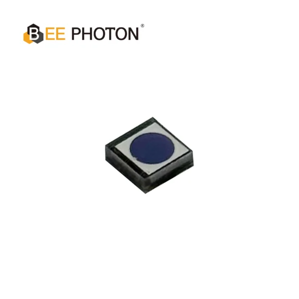
Si phototransistor PTCP Series PTCP001-102
High-sensitivity Silicon Phototransistor designed for precision detection in the 800-1100nm spectral range. This black plastic IR sensor ensures minimal noise and high reliability. Ideal for industrial applications requiring a robust silicon phototransistor with excellent response speed.
How Reverse Voltage Shrinks Junction Capacitance (And Why That’s Huge)
Here’s the part circuit designers lose sleep over: the RC time constant in your front-end amp. That junction capacitance Cj is usually the biggest chunk of it.
When you apply reverse bias, the depletion layer gets thicker. Capacitance drops because it’s basically two plates (the p and n regions) with a wider gap between them. The formula in plain English: junction capacitance Cj is roughly proportional to 1 over the square root of (built-in voltage plus the absolute value of your reverse voltage Vr).
In real numbers, one typical silicon photodiode sees its capacitance fall to about 40% of the zero-bias value at just -3 V, down to 29% at -5 V, and as low as 23% at -15 V. That’s straight from industry application notes we reference daily at BeePhoton.
Lower Cj = smaller RC product = faster rise times and higher cutoff frequencies. For a reverse bias photodiode in a transimpedance amp, this can mean going from a sluggish 100 kHz response to several MHz without changing anything else. We’ve seen it in laser triangulation sensors and optical encoders where every nanosecond counts.
Pro tip from the bench: don’t just crank Vr to the max. There’s a point of diminishing returns once the depletion region is fully extended. After that you’re mostly adding dark current without much extra speed gain.
Why Reverse Bias Photodiode Improves Linearity (And When It Doesn’t)
Linearity is the other big win. In zero-bias mode, at higher light levels the output can start to curve off because carriers don’t get collected efficiently. Apply reverse bias and the stronger electric field pulls those carriers across faster and more completely. Result? A much straighter photocurrent vs. light intensity curve—often linear over six orders of magnitude or more.
Hamamatsu’s technical notes on Si photodiodes point out that reverse voltage helps push the upper limit of linearity higher, which is gold for applications like power meters or medical imaging where you need accurate readings across varying intensities.
But here’s the honest bit: it’s not magic. Push Vr too high and dark current climbs, which can mess with your signal-to-noise ratio in very low-light setups. That’s why we always ask clients about their expected light levels before recommending a specific Vr.
Dark Current, Noise, and the Vr Max Reality Check
Every upside has a downside. Reverse bias photodiode operation does increase dark current—sometimes dramatically as Vr rises. That leakage current adds noise, especially in cooled or low-light designs.
Typical Vr max for Si PIN photodiodes sits around 10–30 V depending on the model. Exceed it and you risk avalanche breakdown or permanent damage. We’ve had customers who learned this the hard way by ignoring the datasheet.
Temperature plays a role too. Dark current roughly doubles every 10°C rise, so if your enclosure gets warm, that Vr you chose at the bench might behave differently in the field.
Picking the Right Vr for Your Si PIN Photodiode Circuit
Circuit designers usually land in one of two camps:
- Speed freaks (fiber comms, LIDAR, scanning) → aim for -5 V to -15 V or whatever the datasheet recommends for max bandwidth.
- Low-noise folks (spectroscopy, medical sensors) → maybe stick closer to -2 V or even zero bias and live with a bit more capacitance.
At BeePhoton our Si PIN photodiodes are built with generous voltage margins and low dark current even under reverse bias. Check out the full lineup here: Si PIN photodiodes.
One anonymous case that still makes me smile: a client building a high-speed optical encoder for industrial automation kept hitting bandwidth limits at zero bias. We suggested switching to a reverse bias photodiode setup at -10 V on our standard Si PIN part. Rise time dropped by over 60%, linearity improved across their full dynamic range, and the system passed final certification on the first try. They ended up ordering in volume—simple tweak, big payoff.
Another time, a medical device team was fighting non-linearity in their pulse oximeter prototype. A modest -5 V reverse bias cleaned up the signal enough that they could drop a costly calibration step.
Si PIN Photodiode with low dark current (350-1060nm) PDCC07-101
Optimize your optical communication systems with the PDCC07-101, a high-performance Si PIN for Data Transmission engineered for precision and reliability. This COB-packaged photodiode features a large Φ3.0mm photosensitive area and a peak sensitivity at 800nm, delivering a fast rise time of 0.18µs and an ultra-low dark current of 2.5pA. Designed to cover a broad spectral range from 350nm to 1060nm, the PDCC07-101 is the ideal Si PIN for Data Transmission solution for ensuring stable, high-speed signal processing in demanding industrial environments.
Common Mistakes and Quick Fixes
- Treating Vr as “more is always better.” Not true once you’re fully depleted.
- Ignoring stray capacitance in the layout—your board traces can wipe out the gains from low Cj.
- Forgetting temperature compensation in the bias circuit.
If you’re sketching a new design right now, drop us a line at info@photo-detector.com or head straight to our contact page for a quick spec review. We’re happy to look at your schematic and suggest the exact Vr sweet spot.
FAQ: Reverse Bias Photodiode Questions We Get All the Time
What exactly is Vr max on a reverse bias photodiode and why does it matter?
Vr max is the highest reverse voltage your photodiode can handle before breakdown or damage. For most Si PIN photodiodes it’s listed in the datasheet (often 10–30 V). Exceeding it risks destroying the junction and spiking dark current permanently. Always stay a bit below the rating for long-term reliability.
Does applying reverse bias always make a photodiode faster?
Yes in almost every practical case. The lower junction capacitance shortens the RC time constant and speeds carrier collection. Real-world datasheets from Thorlabs and Hamamatsu show cutoff frequencies jumping several times higher once you move into photoconductive mode.
How much does reverse bias affect linearity in everyday circuits?
It usually extends the linear range noticeably—sometimes by an order of magnitude at higher light levels. That’s why reverse bias photodiode setups are standard in anything needing accurate analog output across varying intensities.
Is there a downside to using reverse bias photodiode operation in low-light designs?
Dark current goes up, so noise can become an issue if you’re measuring tiny signals. In those cases we often recommend staying at lower Vr or adding cooling.
If you’re still not sure which way to go with your next project, grab one of our Si PIN photodiodes and test it yourself. We stand behind every part with real application support.
Ready to dial in the perfect reverse bias for your design? Whether you need a quick quote, a custom bias recommendation, or just want to talk through your circuit challenges, reach out to the BeePhoton team today. We’ve helped dozens of engineers turn “good enough” photodetector performance into “best in class.” Drop us a note at info@photo-detector.com or browse the full Si PIN photodiode selection here. Let’s make your next optical system faster, more linear, and rock-solid reliable.