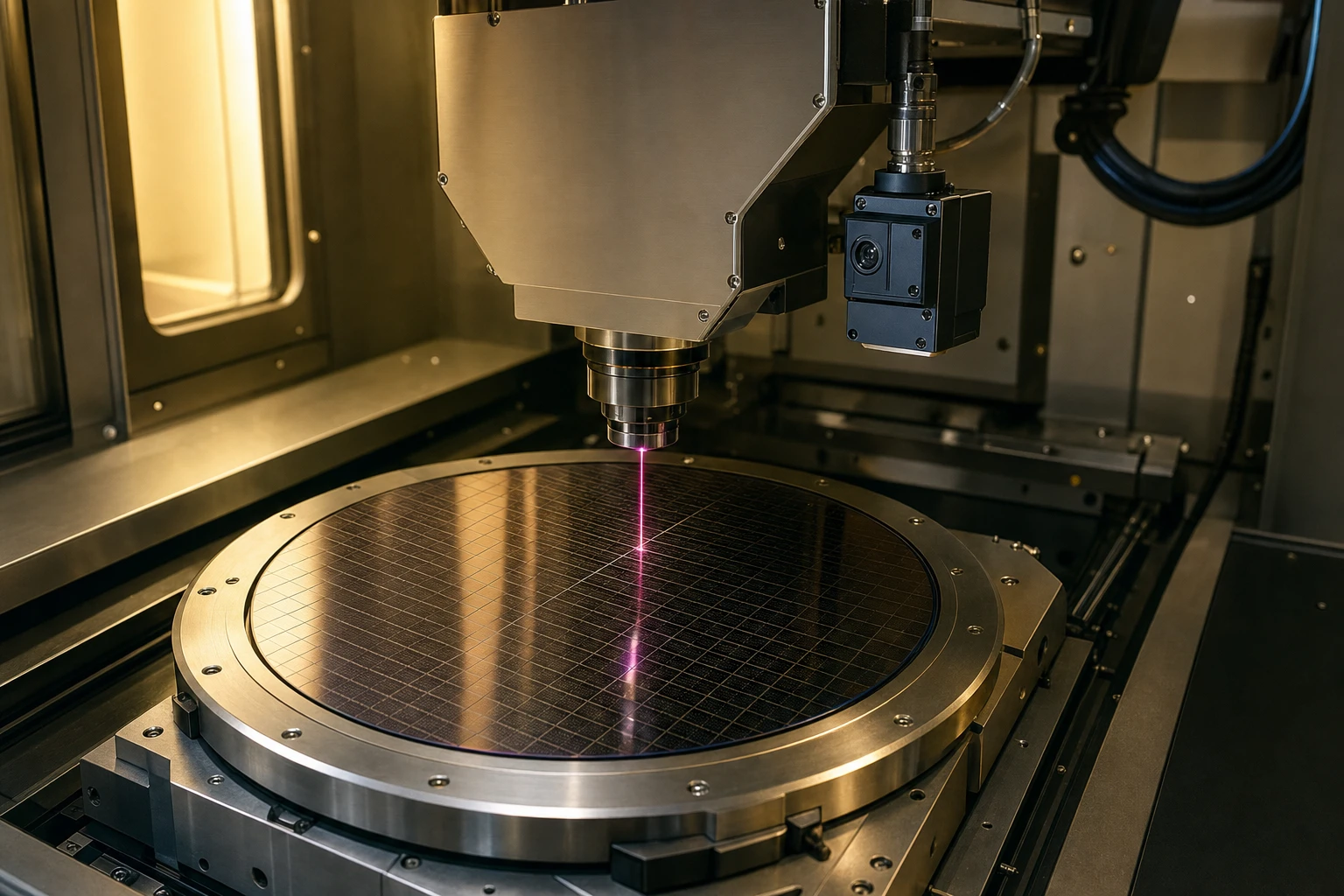
If you have ever spent late nights in the lab trying to squeeze another microradian of accuracy out of a closed-loop galvanometer scanner, you know the absolute pain of position detection. You are tweaking the analog driver board, shielding your cables, and praying that the thermal drift doesn’t ruin your laser marking lines. At the heart of this struggle is the Galvo-Positionsrückmeldesensor. It is the unsung hero that tells the driver board exactly where the mirror is pointing. If your Galvo-Positionsrückmeldesensor isn’t feeding clean, low-noise data back to your PID loop, your high-speed scanner is basically flying blind.
When we talk about galvanometer position sensing, we usually mean an optical setup. An infrared emitter shines on a moving vane attached to the motor shaft, and the shadow or reflection falls on a segmented photodiode. But here is the real kicker: if you are a closed-loop driver developer, you have definitly run into the issue of weak reflected light. Many off-the-shelf optical galvanometer sensor options just don’t have the sensitivity needed to handle rapid changes without sinking into the noise floor. That is why choosing the right Galvo-Positionsrückmeldesensor components—specifically high-sensitivity near-infrared (NIR) silicon chips—is the make-or-break decision for your system.
Why Weak Signals and Thermal Drift Destroy Accuracy
Let’s look at what is actually happening inside your optical galvanometer sensor. To keep the rotor weight down, the physical shutter or vane has to be tiny and feather-light. A heavier vane means more inertia, which kills your step response time. But a smaller vane means less surface area to reflect or block light, resulting in an incredibly weak optical signal hitting your Galvo-Positionsrückmeldesensor.
When the light is weak, your signal-to-noise ratio (SNR) goes to trash. To get a usable feedback voltage, you have to pump up the gain on your transimpedance amplifier (TIA). But when you pump up the gain, you are also amplifying all the thermal noise, shot noise, and high-frequency interference. Suddenly, your steady-state position starts jittering. This is why a premium Galvo-Positionsrückmeldesensor is so critical; it ensures that even with a tiny light signal, you still get a clean, usable output.
Another massive headache is thermal drift. As the galvanometer coils heat up during heavy duty cycles, that heat transfers straight to the Galvo-Positionsrückmeldesensor. If you are using a cheap, standard photodiode, its dark current—the current that flows even when there is zero light—starts climbing exponentially. Here is a quick rule of thumb: dark current roughly doubles for every 10 degrees Celsius rise in temperature. If your Galvo-Positionsrückmeldesensor experiences a 30C temperature swing inside the housing, your position signal drifts, and your laser scanner’s zero point moves. Your laser cuts are no longer aligning, and your customer is calling to complain about calibration issues. To fix this, you need a high-end Galvo-Positionsrückmeldesensor designed with low dark current and high responsivity in the NIR band.
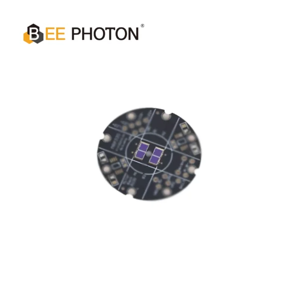
Si-PIN-Photodioden für Galvo PDC-C2928-NIR-B
Optimieren Sie Ihre Scanvorgänge mit unserem 940-nm-PIN-Fotodiodenchip PDC-C2928-NIR-B. Dieser 940-nm-PIN-Fotodiodenchip gewährleistet eine präzise Galvo-Positionserfassung und ein geringes Rauschen.
The Math of Differential Position Sensing
Let’s break down the actual math behind how a Galvo-Positionsrückmeldesensor calculates position. Typically, you use a split or segmented photodiode—like a dual-element or quad-element array. Let’s call the photocurrents from the two main segments Segment A (I_A) and Segment B (I_B). The Galvo-Positionsrückmeldesensor position feedback signal (S) is calculated using a ratiometric formula to cancel out common-mode noise and light source fluctuations:
S = (I_A – I_B) / (I_A + I_B)
This looks simple on paper, but let’s see how dark current (I_d) and responsivity (R) mess things up in the real world. Let’s say the light power hitting segment A is P_A and segment B is P_B. The actual currents generated in your Galvo-Positionsrückmeldesensor are:
I_A = (R * P_A) + I_dA
I_B = (R * P_B) + I_dB
If you plug these into your formula, the Galvo-Positionsrückmeldesensor position feedback signal becomes:
S = ((R * P_A + I_dA) – (R * P_B + I_dB)) / ((R * P_A + I_dA) + (R * P_B + I_dB))
In an ideal world, the dark currents are perfectly matched (I_dA = I_dB) and extremely small. If they are small enough to ignore, the R cancels out, and you get:
S = (P_A – P_B) / (P_A + P_B)
But what happens when your Galvo-Positionsrückmeldesensor gets hot, and the dark currents increase unevenly? If I_dA does not equal I_dB due to thermal gradients across the silicon die, or if the dark current becomes a significant fraction of the weak photocurrent, the ratiometric calculation in your Galvo-Positionsrückmeldesensor fails. The position signal drifts, and your closed-loop controller thinks the mirror has moved when it hasn’t. This is why a high-quality Galvo-Positionsrückmeldesensor requires a specialized Galvo-Feedback-Photodiode chip with extremely low dark current—typically in the picoampere range—and excellent thermal matching between segments.
Why High-Sensitivity NIR Chips are the Ultimate Fix
If you want to beat the weak signal problem, you have to optimize the optical link budget. This means matching your light source wavelength to the peak responsivity of your Galvo-Positionsrückmeldesensor. Most high-speed position sensing systems use infrared LEDs or lasers operating at 920nm or 940nm because these wavelengths are invisible to the human eye and don’t interfere with visible laser beams.
Standard silicon photodiodes have their peak sensitivity around 800nm to 850nm. When you hit them with 940nm light, their responsivity drops significantly—often down to 0.4 A/W or lower. This is a massive waste of precious photons. By switching to high-sensitivity NIR chips, you get a Galvo-Positionsrückmeldesensor with responsivity optimized specifically for 920nm and 940nm, reaching up to 0.6 A/W or higher.
Let’s think about what that means for your hardware design. If your Galvo-Positionsrückmeldesensor has 50% higher responsivity, you can turn down the drive current of your feedback LED. This keeps your galvo rotor cooler, reducing thermal drift right at the source of your Galvo-Positionsrückmeldesensor. Also, you can decrease the feedback resistor in your transimpedance amplifier. A smaller feedback resistor means lower thermal noise (Johnson noise), which instantly cleans up your position feedback signal and reduces jitter. When you are aiming for sub-microradian repeatability in your galvanometer position sensing design, these small physical changes make a night-and-day difference for your Galvo-Positionsrückmeldesensor.
Handpicked NIR Photodiode Chips for Your Designs
As someone who has looked at dozens of datasheets, I know that finding a reliable supplier for raw photodiode chips can be a nightmare. B2B buyers and hardware developers need chips that are rugged, thermally stable, and easy to package into custom galvo optical heads. This is where BeePhoton comes in. They have some seriously impressive silicon PIN chips that are specifically tailored for industrial Galvo-Positionsrückmeldesensor applications.
Let’s talk about three specific chips that are absolute game-changers for any Galvo-Positionsrückmeldesensor development project.
First up is the PDC-C2928-NIR-B. This is a 940-nm-PIN-Fotodioden-Chips designed specifically to maximize responsivity in the near-infrared spectrum. If your optical galvanometer sensor uses a 940nm LED light source, this chip is your best bet. It features an active area of 2.9 by 2.8 mm, giving you plenty of surface area to capture the modulated beam, and its low dark current keeps your noise floor incredibly low even when operating in high-temperature environments. It makes an excellent core component for a high-performance Galvo-Positionsrückmeldesensor.
Next, we have the PDC-C2929. If your system design is optimized for slightly shorter infrared wavelengths, this 920nm silicon PIN photodiode is a fantastic choice. It delivers exceptional quantum efficiency at 920nm while maintaining a fast response time. When building a Galvo-Positionsrückmeldesensor that needs to operate at high bandwidths (think 10 kHz or higher closed-loop bandwidth), the low capacitance of the PDC-C2929 ensures that your sensor doesn’t introduce phase lag into your control loop. This makes the PDC-C2929 a perfect fit for a dynamic Galvo-Positionsrückmeldesensor.
Finally, for systems requiring true differential or multi-element position tracking, you should look at the PDC-2C3432-NIR-B. This is a segmentierter PIN-Fotodioden-Chip featuring two independent elements on a single monolithic silicon die. Having both segments on the same piece of silicon is crucial because they share the exact same thermal enviroment. Any temperature changes affect both segments equally, which naturally cancels out thermal drift in your ratiometric position calculations. It is hands-down one of the best components you can get for a high-precision Galvo-Positionsrückmeldesensor.
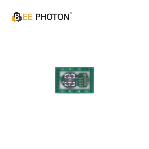
Si-PIN-Photodioden für Galvo PDC-2C3432-NIR-B
Die PDC-2C3432-NIR-B ist ein spezialisiertes segmentierter PIN-Fotodioden-Chip entwickelt für präzise differentielle Positionsrückführung in Hochgeschwindigkeits-Galvanometerscannern. Die Integration dieses zweikanaligen segmentierter PIN-Fotodioden-Chip ermöglicht Systemen eine genaue Winkelverfolgung bei minimalem Signalrauschen.
Comparing the Technical Specs
Let’s put these specs side by side so you can see what actually matters for your Galvo-Positionsrückmeldesensor design. As B2B buyers, we want hard numbers, not marketing fluff.
| Parameter | PDC-C2928-NIR-B | PDC-C2929 | PDC-2C3432-NIR-B |
|---|---|---|---|
| Peak-Wellenlänge | 940 nm | 920 nm | 940 nm (NIR optimized) |
| Aktive Fläche Größe | 2.9 mm x 2.8 mm | 2.9 mm x 2.9 mm | Segmented Dual Array |
| Struktur | Single PIN Chip | Single PIN Chip | Segmented Dual PIN |
| Dark Current (Typical) | Low (picoamps) | Extrem niedrig | Ultra-low, matched elements |
| Übergangskapazität | Low (for high speed) | Very Low (high bandwidth) | Matched capacitance |
| Application Suitability | General NIR feedback | High-bandwidth feedback | High-precision differential feedback |
When choosing a chip for your Galvo-Positionsrückmeldesensor, you have to balance active area size with junction capacitance. A larger active area makes optical alignment much easier because you don’t have to sweat sub-micron mechanical tolerances. However, a larger active area also means higher junction capacitance, which can slow down your sensor’s response time.
Fortunately, the PIN structures used in these BeePhoton chips are engineered to keep capacitance low even with generous active areas. This means you don’t have to compromise on alignment tolerances to get the high speed needed for your closed-loop control system. Using these optimized chips in your Galvo-Positionsrückmeldesensor gives you the best of both worlds: robust mechanical assembly and lightning-fast positioning feedback. A well-designed Galvo-Positionsrückmeldesensor doesn’t just work; it elevates your entire scanner’s performance.
A Spicy Take on Software Filtering
A lot of software guys think they can write some fancy digital filtering or Kalman filter code to clean up a noisy analog position signal. Let’s be real: that is a complete joke. If you try to fix bad analog hardware with software, you are just masking the problem and adding massive processing latency to your control loop. In high-speed galvo scanning, latency is the ultimate killer of stability. You want to fix the optical link budget at the hardware level first, not try to patch a junk signal after the fact.
An Anonymous B2B Success Story
Let me share a quick story from the field. A couple of years ago, a mid-sized B2B client of mine was developing a 150-watt fiber laser marking system. They were designing their own closed-loop galvo driver from scratch, trying to beat the high costs of imported scanning heads. They had everything ready, but their prototype kept experiencing what we call ‘line wiggle’ or jitter during long runs. When the laser marker had been running for twenty minutes, the marking lines would start to blur. They thought it was a software bug in their PID loop or electrical noise from the laser power supply. They spent weeks shielding cables and rewriting code, but nothing worked. All because of a poorly matched Galvo-Positionsrückmeldesensor.
Finally, we looked at the optical galvanometer sensor assembly. They were using standard, cheap visible-light photodiodes as their Galvo-Positionsrückmeldesensor receivers, paired with a 940nm LED. The responsivity at 940nm was so weak that they had to use a massive 1M ohm feedback resistor on their TIA. As the galvo motor heated up to 55C, the dark current of those cheap photodiodes went through the roof, shifting the position bias.
We helped them swap out those generic parts for the segmentierten PIN-Photodioden-Chip PDC-2C3432-NIR-B. Because this chip is optimized for NIR wavelengths, their signal strength instantly tripled. They were able to drop their TIA feedback resistor down to 200k ohms, which slashed their analog noise floor. Plus, because the two elements are monolithic, the thermal drift vanished. The ‘line wiggle’ disappeared, and they successfully launched their scanner at a fraction of the cost of importing. It just goes to show that a high-quality Galvo-Positionsrückmeldesensor is the foundation of any high-precision scanner. If you don’t have a reliable Galvo-Positionsrückmeldesensor, your high-end driver board is basically useless.
Practical Tips for Integrating NIR Chips into Your Galvo Feedback Systems
If you are going to integrate these high-sensitivity chips into your Galvo-Positionsrückmeldesensor design, there are a few practical rules of thumb you should follow to make sure you get the best performance.
First, keep your transimpedance amplifier (TIA) as physically close to the Galvo-Positionsrückmeldesensor as humanly possible. The output current of these photodiode chips is in the microamp range. If you run long, unshielded wires from the photodiode to your driver board, those wires will act as antennas, picking up massive amounts of electromagnetic interference (EMI) from the galvo’s high-current drive coils. Put the TIA right on the back of the sensor board to convert that weak current into a robust voltage signal before sending it down the cable. A noisy environment will absolutely destroy the accuracy of your Galvo-Positionsrückmeldesensor.
Second, pay attention to optical alignment. When setting up your Galvo-Positionsrückmeldesensor, make sure your light source is well-collimated. If the light beam spreading is too wide, you will get stray reflections off the inside of the galvo housing. This stray light acts as a constant DC offset, which reduces your usable dynamic range and can saturate your receiver if you aren’t careful. A well-aligned Galvo-Positionsrückmeldesensor is the difference between a high-yield production line and a massive waste of testing time.
Lastly, design a stable mounting bracket for your Galvo-Positionsrückmeldesensor. Even a microscopic physical wiggle in the sensor mount will look like a massive position shift to your closed-loop controller. Use materials with low thermal expansion coefficients, like aluminum or specialized engineering plastics, to ensure that the physical distance between your emitter, vane, and photodiode remains rock-solid across your entire operating temperature range. By combining these practical board-level design practices with high-performance silicon chips, you can build a Galvo-Positionsrückmeldesensor that rival the specs of any high-end commercial scanner on the market.
Si-PIN-Photodioden für Galvo PDC-C2929
Der PDC-C2929 ist ein kostengünstiger 920-nm-Silizium-PIN-Photodioden-Chip. Diese 920-nm-Silizium-PIN-Photodiode bietet eine stabile und wirtschaftliche Scanner-Positionsverfolgung.
Frequently Asked Questions about Galvo Feedback Systems
Warum sollte ich eine segmentierte PIN-Fotodiode gegenüber einem einzelnen PIN-Chip für meinen Galvo-Positionsrückmeldungssensor bevorzugen?
A single PIN photodiode can only measure total light intensity, which isn’t very useful for position tracking unless you use a very complex graduated mask. A segmented photodiode, like the PDC-2C3432-NIR-B, allows for differential sensing. By comparing the light falling on Segment A versus Segment B, you get a direct, linear representation of position that naturally filters out common-mode noise, such as fluctuations in the light source’s brightness. That’s why most professional designs rely on a segmented Galvo-Positionsrückmeldesensor da sie einfach wesentlich stabiler ist.
Wie trägt die Auswahl eines 940-nm-NIR-Chips zur Reduzierung von Umgebungslichtinterferenzen in einem Galvo-Positionsrückmeldesensor bei?
Die meisten industriellen Umgebungen sind erfüllt von sichtbarem Streulicht durch Decken-LEDs, Computermonitore und Fabrikfenster. Wenn Ihr Galvo-Positionsrückmeldesensor empfindlich auf sichtbares Licht reagiert, wird dieses Umgebungsrauschen Ihr Rückkopplungssignal verfälschen. Durch die Verwendung eines 940-nm-NIR-Chips wie dem PDC-C2928-NIR-B und der Kombination mit einem physischen Tageslicht-Sperrfilter blockieren Sie praktisch das gesamte sichtbare Umgebungsrauschen. Dies ermöglicht Ihrem Scanner einen zuverlässigen Betrieb in hellen Fabrikhallen, ohne dass ein vollständig versiegeltes, lichtdichtes Gehäuse erforderlich ist. Dieses einfache Hardware-Upgrade macht Ihr Galvo-Positionsrückmeldesensor nahezu immun gegen Büro- oder Fabrikbeleuchtung.
Kann ich den PDC-C2929-Chip mit einer 850-nm-Lichtquelle für meinen Galvo-Positionsrückmeldungssensor verwenden?
Ja, das ist absolut möglich. Das PDC-C2929 verfügt über eine breite spektrale Empfindlichkeit von 350 nm bis 1100 nm. Obwohl es für eine hohe Responsivität bei 920 nm optimiert ist, erbringt es auch bei 850 nm eine außergewöhnlich gute Leistung. Wenn Ihr System jedoch einen 920-nm-Emitter unterstützt, erzielen Sie durch die Kombination mit dem PDC-C2929 die absolut höchste Quanteneffizienz und das beste Signal-Rausch-Verhältnis für Ihre Galvo-Positionsrückmeldesensor.
Take Your Galvanometer Designs to the Next Level
Building a closed-loop galvanometer scanner requires more than just smart PID algorithms—it starts with the physics of your feedback loop. If your position feedback signals are buried in noise or shifting with temperature, your system will never hit its true potential.
That’s where optimized NIR photodiode chips make all the difference. By matching your optical galvanometer sensor’s receiver to high-sensitivity silicon like the BeePhoton NIR PIN series, you instantly slash thermal drift, boost your signal strength, and lower your analog noise floor.
Imagine delivering a laser scanning system with sub-microradian repeatability, zero thermal warm-up drift, and rock-solid reliability that keeps your B2B customers coming back. No more endless troubleshooting in the lab. No more dealing with expensive imported components that squeeze your profit margins. With custom, high-performance silicon chips, you can take complete control of your hardware design and manufacturing costs.
Don’t let weak feedback signals hold your designs back. If you are currently designing or upgrading a closed-loop scanner, reach out to the engineering team at BeePhoton. You can explore their full lineup of high-sensitivity photodiode chips, request custom silicon packaging, or get a quick quote by visiting their Kontakt Seite or sending an email directly to info@photo-detector.com. Let’s work together to build a faster, more precise Galvo-Positionsrückmeldesensor for your next project.