Imagine you are three weeks into a major industrial motor drive launch. The prototypes worked fine, but suddenly, half the units coming off the pre-production line are throwing random phase errors at high speeds. Your team is scrambling. You check the code, you swap the main microcontroller, you recalibrate the photodiode sensor array. Nothing works.
Eventually, you look at the optical alignment. It turns out someone in procurement swapped out the specified light source for a generic infrared LED they found on a broad-line distributor’s catalog because it looked identical and saved forty cents a unit.
This is the classic nightmare scenario when choosing an encoder LED emitter without understanding the raw physics of optical feedback systems. It happens far more often than you think in this industry.
People assume that any light-emitting diode emitting at the right wavelength can do the job. But in reality, this specific encoder LED emitter has a massive impact on the overall precision, noise margin, and field reliability of your rotary or linear feedback system. How the encoder LED emitter functions directly determines whether your system reads sharp, clean transitions or a blurry mess of optical noise. Your specific encoder LED emitter selection is the heart of the entire optical sensor. To get the right encoder LED emitter, you have to look past the basic marketing bullet points. Let’s break down the technical realities of selecting an encoder LED emitter so you can avoid buying the wrong parts and save your company from expensive field recalls.
The Realities of Beam Collimation: Why the Emission Angle is Everything
The most vital parameter of any encoder LED emitter is the emission angle, which is often listed as the half-intensity angle in technical datasheets.
The dirty secret of the optical component industry is that most standard, off-the-shelf LEDs are designed to scatter light. They are built for indicators, general illumination, or remote controls where a wide, generous beam is a feature. But when you are choosing a quality encoder LED emitter, a wide beam is your worst enemy. Every premium encoder LED emitter must focus its light as tightly as possible.
Using an uncollimated encoder LED emitter means light spreads out rapidly, hitting the codewheel slits at wide, sloppy angles. As those light rays pass through the fine slits of the disk, they do not cast straight, clean shadows. Instead, the light bends and scatters, bleeding into the adjacent channels of your photodiode array. This causes terrible signal crosstalk and degrades your phase margin.
To help visualize how beam width impacts your signal quality, let’s contrast the two designs:
- Wide Beam LED (Generic Indicator Style): Light spreads out widely. Rays hit the disk slits at highly angled paths. This blurs the shadow edges on the sensor array, leading to high crosstalk and weak signal resolution.
- Narrow Beam LED (Dedicated Point-Source Style): Light rays travel in near-perfect parallel paths. The rays hit the disk slits straight on, casting incredibly sharp shadow edges onto the sensor. This results in high signal contrast and maximum precision.
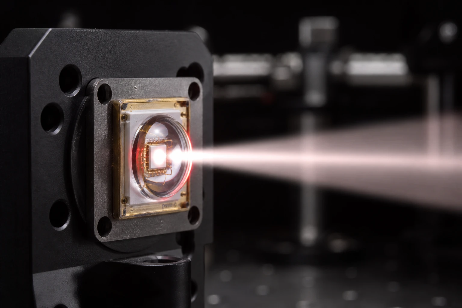
To get clean, square wave signals with a reliable 50/50 duty cycle, you need a highly collimated beam. A high-grade encoder LED emitter will feature a very tight emission angle, usually under 5 degrees. The smaller the angle, the closer the light rays are to being perfectly parallel.
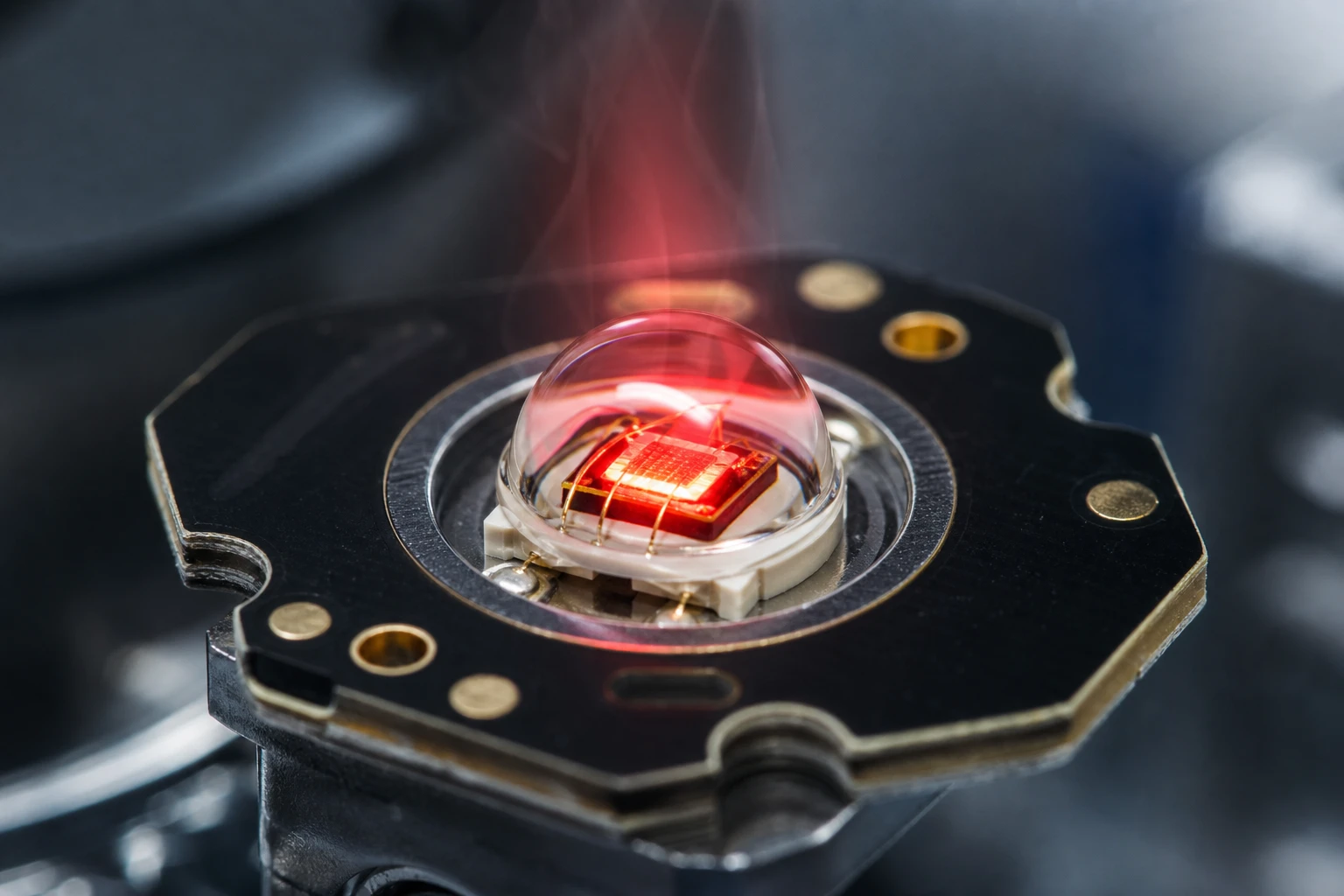
Before buying an encoder LED emitter, look at how the manufacturer achieves this narrow angle. This particular encoder LED emitter might use a glass ball lens or a specialized double-convex lens molded directly into the header. Compare that to a cheap encoder LED emitter which uses cheap epoxy that degrades and yellows over time, altering the beam path.
En BeePhoton, our high-quality encoder LED emitter options are designed from the ground up with precision micro-lenses to maintain a sharp, tightly focused beam even under harsh operating conditions.

Fuente de luz LED serie E850-15-301
Como proveedor experto en fuentes de luz B2B, Bee Photon proporciona componentes TO18 de alta fiabilidad. Nuestras fuentes de luz uniformes garantizan un rendimiento estable para sus proyectos.
Doing the Math: The Physics of Penumbra Blur
When integrating your encoder LED emitter into a physical system, you have to deal with the geometric limits of shadow casting. When light passes through an encoder disk, we want to minimize the fuzzy edges of the shadow cast onto the receiver. This fuzzy, semi-shaded region is called the penumbra.
You can calculate the width of this penumbra blur using a simple geometric formula.
Penumbra Blur Width (Pb) = W * (d2 / d1)
Dónde:
- W is the physical size of the active light-emitting aperture.
- d2 is the mechanical gap between the codewheel disk and the photodiode detector array.
- d1 is the distance from the actual emitting surface of the LED to the codewheel disk.
If you want a highly precise signal, you want your penumbra blur to be as close to zero as possible. Looking at the math, you have a few options to make this happen. You can try to make the gap between the disk and the sensor (d2) microscopic, but if you do that, a tiny wobble in the motor shaft will cause the disk to crash into the sensor. You could also make the distance from the light source to the disk (d1) huge, but this makes your physical encoder housing massive.
This is why the active area of an encoder LED emitter is so critical. If your encoder LED emitter has a massive emitting chip (like 350 microns), the penumbra blur will be huge. A point-source encoder LED emitter solves this by using a tiny active emitting aperture, often between 50 and 150 microns.
Choosing a tiny encoder LED emitter keeps the value of W very low, which mathematically minimizes the shadow blur even if your mechanical alignment tolerances drift during high-speed rotations. This is why an encoder LED emitter with a tiny point-source aperture is vastly superior to generic infrared LEDs for high-resolution positioning.
Wavelength Dilemma: Matching the Emitter to Your Photodetector
The wavelength of an encoder LED emitter is another area where minor purchasing mistakes lead to catastrophic field failures. To get the strongest signal with the least amount of electrical noise, you must match your emitter wavelength with the spectral responsivity curve of your silicon photodetector.
An 850nm encoder LED emitter is the historic workhorse of the industry. This is because silicon-based phototransistors and photodiode arrays have their peak sensitivity in the near-infrared (NIR) spectrum, specifically between 850nm and 880nm.
However, high-resolution modern encoders are beginning to use shorter wavelengths to push the limits of precision:
- Infrared (850nm – 880nm): Highly efficient, matches the natural peak sensitivity of silicon photodetectors, and has a very long operational life.
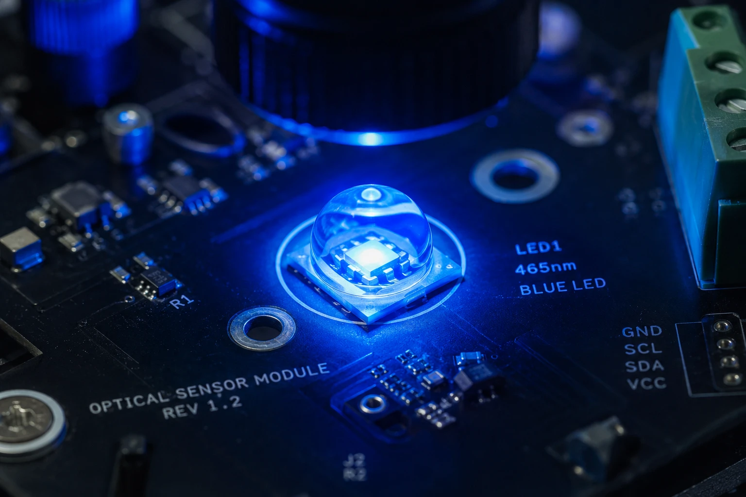
- Blue (465nm): Shorter wavelengths experience significantly less optical diffraction when passing through extremely narrow slits. A blue encoder LED emitter allows you to use incredibly fine line counts on tiny glass disks.
- Red (650nm): A middle-ground option that reduces diffraction compared to infrared while offering better photodiode sensitivity than blue.
Why a red encoder LED emitter or blue emitter might not always be the perfect drop-in replacement comes down to sensor compatability. Silicon detectors are much less sensitive to blue light. If you switch to a blue light source, your receiver circuit will require much higher gain, making your system more sensitive to ambient electrical noise.
Many low-cost encoder LED emitter modules sold on the cheap market use 940nm wavelengths because they are widely produced for television remote controls. But before specifying an encoder LED emitter with a 940nm wavelength, check your detector’s datasheet. You might find that your signal margin drops by up to 30% simply because the silicon isn’t tuned to receive 940nm light efficiently.
The exact encoder LED emitter spectrum you choose must be a conscious design decision, not a random choice based on what is currently cheapest on a distributor’s website. This is where custom encoder LED emitter design can save you weeks of optimization.
Thermal Aging and De-rating: Keeping Your Light Source Alive
How you drive your encoder LED emitter directly dictates its operating lifespan. In industrial environments, like inside a sealed servo motor housing on a factory floor, ambient temperatures can easily exceed 85 degrees Celsius.
When an encoder LED emitter is subjected to high heat, two main issues occur: thermal droop (a natural drop in light output) and accelerated physical degradation.
The degradation of optical power over time can be represented by this classic formula:
L(t) = L(0) * e^(-A * t)
Dónde:
- L(t) is the optical output power at time t.
- L(0) is the initial optical power at day one.
- e is the mathematical constant (approximately 2.718).
- A is the degradation acceleration factor, which is highly dependant on both junction temperature and drive current.
Running your encoder LED emitter at its absolute maximum rated forward current (say, 80mA) in a hot environment causes the degradation factor to spike. Within a year, the light output might drop by half.
To keep the encoder LED emitter bright and reliable for over 100,000 hours, smart design engineers use de-rating. A de-rating strategy means running the emitter far below its maximum capacity.
A de-rated encoder LED emitter might be rated for 50mA, but you design your circuit to run it at a stable 15mA or 20mA. If the encoder LED emitter is driven conservatively, it runs much cooler, protecting the semiconductor junction.
Additionally, you can design a feedback loop using a monitoring photodiode. As your encoder LED emitter slowly dims over years of operation, the control circuit automatically increases the drive current slightly to maintain a perfectly consistent level of brightness.
Fuente de luz LED serie E940-15-301
Nuestra fuente de luz para conmutadores ópticos de alto rendimiento se presenta en un compacto encapsulado TO18. Esta fuente de luz para interruptores ópticos garantiza una uniformidad y fiabilidad excelentes para las telecomunicaciones.
Technical Specifications Comparison
Choosing the best encoder LED emitter requires looking closely at the parameter trade-offs. Our comparison of encoder LED emitter types below highlights the difference between industrial-grade components and cheap alternatives:
| Parameter Specification | Premium Point-Source Encoder Emitter | Generic Infrared LED | Low-Cost “Compatible” Emitter |
|---|---|---|---|
| Longitud de onda pico | 850 nm (or 465 nm Blue) | 940 nm | 850 nm |
| Emission Half-Angle | 2.5 degrees | 30 degrees | 12 degrees |
| Aperture / Emitting Size | 50 microns (Point Source) | 350 microns | 200 microns |
| Rise & Fall Time | 15 nanoseconds | 500 nanoseconds | 120 nanoseconds |
| Temperatura de funcionamiento | -40 to +115 degrees C | -25 to +75 degrees C | -30 to +85 degrees C |
| Packaging Style | TO-46 Metal Can / Ceramic SMD | Epoxy Molded Plastic | Molded Plastic with dome lens |
Looking at this data, you can quickly see why a standard indicator LED is completely useless for precision feedback. If your motor is spinning at 10,000 RPM, an emitter with a slow 500-nanosecond rise time cannot keep up. The output pulses will become rounded and distorted. A premium encoder LED emitter with a 15-nanosecond rise time easily tracks high-frequency rotations without any signal lag.
An Inside Look: A Real-World Sourcing Lesson
Let’s look at a real-world case where component substitution went completely wrong. A European manufacturer of high-end CNC machining centers was building optical feedback modules for their axis drives. During prototyping, their engineers used a high-performance encoder LED emitter with a hermetically sealed glass ball lens. The system worked beautifully in their clean testing facility.
However, when the production run started, the purchasing department substituted the original encoder LED emitter for a cheaper, plastic-molded alternative that claimed to have identical electrical specifications.
Within six months of field deployment, CNC machines in various factories began experiencing positioning drift during long, intensive machining jobs. This drift ruined thousands of dollars in machined aerospace parts and severely damaged the manufacturer’s reputation.
We analyzed the failed encoder modules and found two major culprits:
- The replacement emitter had a 15-degree beam angle rather than the 3-degree angle of the original. This caused massive optical crosstalk at higher temperatures.
- The cheap plastic package of the replacement LED was outgassing under high operating temperatures. This outgassing deposited a thin, cloudy film on the optical mask, scattering the light even further.
Replacing the old encoder LED emitter with a high-reliability encoder LED emitter featuring a metal TO-46 can and glass lens completely solved the issue. Sourcing a proper encoder LED emitter might cost fifty cents more upfront, but when the new encoder LED emitter was implemented, it saved the manufacturer tens of thousands of dollars in warranty claims and field service hours.
Mechanical Packaging Options and Integration
How you physically mount your encoder LED emitter is just as important as its optical specs. Emitters are generally available in three physical styles:
- TO-46 Metal Can Emitters: These classic packages feature a metal header and a hermetically sealed glass lens. They provide the absolute best heat dissipation and are completely immune to chemical outgassing. They are the ideal choice for heavy industrial, automotive, and aerospace applications.
- SMD (Surface Mount) Emitters: These are designed for automated pick-and-place assembly lines. A modern SMD encoder LED emitter will feature a molded dome lens over the chip to achieve collimation. While highly convenient for compact designs, your assembly line must maintain incredibly tight placement tolerances to avoid aligning the beam off-center.
- Bare Die Emitters (Chip-on-Board): High-volume, highly integrated designs sometimes mount a bare-die encoder LED emitter directly onto the encoder circuit board. While this saves physical space, it requires specialized cleanroom assembly and precise mechanical alignment of an external lens.
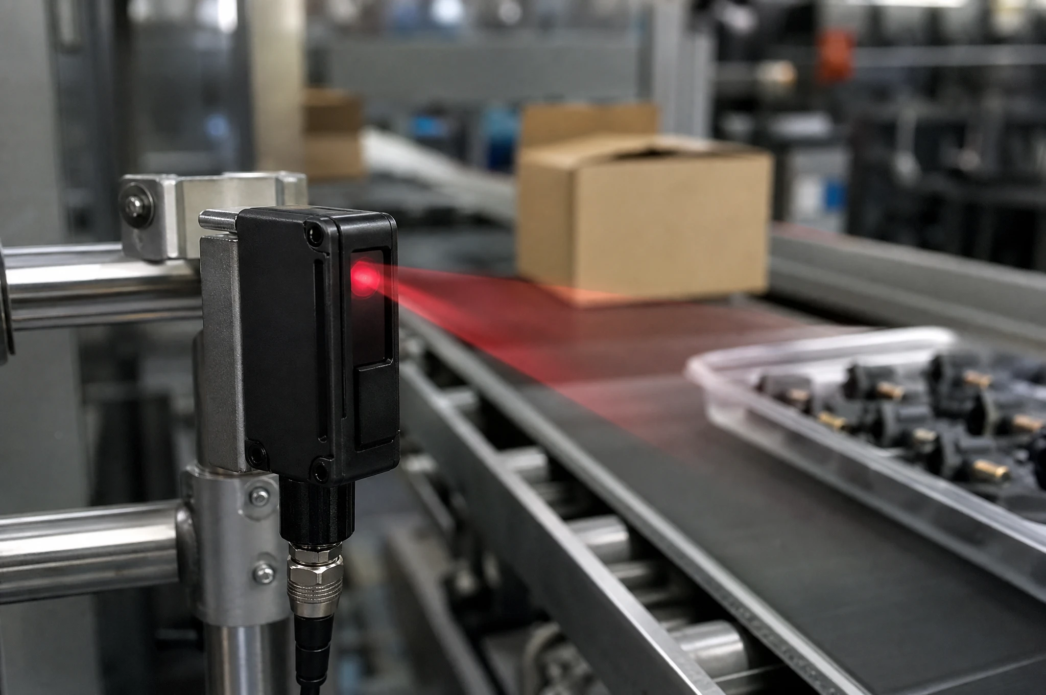
LED NIR E850-25-001-L20
El E850-25-001-L20 es un equipo de alto rendimiento LED NIR de 855 nm diseñado para aplicaciones industriales exigentes. Fabricado por Bee Photon, este emisor de infrarrojos presenta un estrecho ángulo de emisión de 20 grados, que proporciona una alta intensidad radiante de 25 mW/sr adaptada a la detección de precisión. Su robusto diseño garantiza una alta fiabilidad y un rendimiento constante en un amplio rango de temperaturas de funcionamiento.
Preguntas más frecuentes (FAQ)
1. Can I use a normal LED as an encoder LED emitter?
No, you really shouldn’t. Normal LEDs are designed for indicators or general lighting, meaning they have wide beam angles (often 30 degrees or more) and large active emitting areas. If you attempt to use one of these as an encoder LED emitter, the light will scatter, causing massive optical crosstalk and making it impossible for your photodetector to read the fine lines on your codewheel.
2. What is the best wavelength for an encoder LED emitter?
For almost all standard industrial encoders, 850nm is the absolute best choice. This wavelength perfectly matches the peak sensitivity of silicon photodetectors. However, if you are designing an ultra-high-resolution encoder with microscopic lines, a blue encoder LED emitter (465nm) is superior because shorter wavelengths reduce optical diffraction.
3. Why does my encoder LED emitter drop in brightness over time?
All LEDs degrade naturally as they age, but high operating temperatures and high drive currents accelerate this process. If your encoder LED emitter is driven at its maximum current inside a hot motor housing, its brightness can drop by half within a year. You can prevent this by de-rating the drive current and choosing an emitter designed for high-temperature stability.
4. Where can I source a custom encoder LED emitter with specific beam angles?
You can source custom collimated emitters directly from specialized optoelectronic manufacturers. At BeePhoton, we provide custom package configurations, custom wavelengths, and precision alignment services to ensure you get a light source that matches your encoder’s mechanical tolerances perfectly.
Need the Perfect Light Source for Your Optical Encoder?
Sourcing precision optical components shouldn’t be a game of trial and error. If you need a reliable encoder LED emitter that balances tight beam collimation, long-term thermal stability, and budget constraints, our engineering team is here to help.
En BeePhoton, we specialize in the design and manufacture of high-reliability light sources engineered specifically for demanding optical sensors. A precision-engineered encoder LED emitter from our inventory ensures your feedback systems deliver maximum signal contrast, minimum noise, and years of trouble-free field operation.
Don’t risk costly field failures or assembly-line delays. Explore our full range of fuente de luz de codificador óptico options today to find the perfect fit for your design.
To request a custom quote or discuss your specific design requirements, drop our engineering team an email at info@photo-detector.com or send us a message through our official página de contacto. Our specialized encoder LED emitter designs are ready to take your system’s precision to the next level!