The Reality of Choosing a Detector
Look, finding a decent photo-detector for your custom board usually involves tearing your hair out while cross-referencing half a dozen datasheets. Alot of manufacturers massage their numbers. They give you a beautiful junction capacitance spec, but hide the fact that they tested it at a massive reverse bias that will completely fry your dark current noise budget.
If you are an engineer trying to build an optical switch, a laser alignment tool, or a pulse oximetry sensor, you need raw, unadulterated facts. Today, we are going to do a proper photodiode datasheet explained session. We are going to rip apart the specs of the PDCP08-501, a silicon PIN photodiode from the Beephoton PDCP08 series.
Honestly, my controversial take for the day is that 80% of optical engineers over-spec their reverse bias voltage. You don’t always need to slam 10V across your diode just to make it fast. Sometimes a 0V or low-bias setup is perfectly fine if you know how to handle the transimpedance amplifier (TIA) stage, and it saves you from massive dark current headaches. We will look at exactly how the PDCP08-501 behaves in both scenarios.
Let’s break down what makes the PDCP08-501 tick, the physics behind its performance, and how to actually design this thing into your next PCB without looking like an idiot.
What Even Is the PDCP08-501?
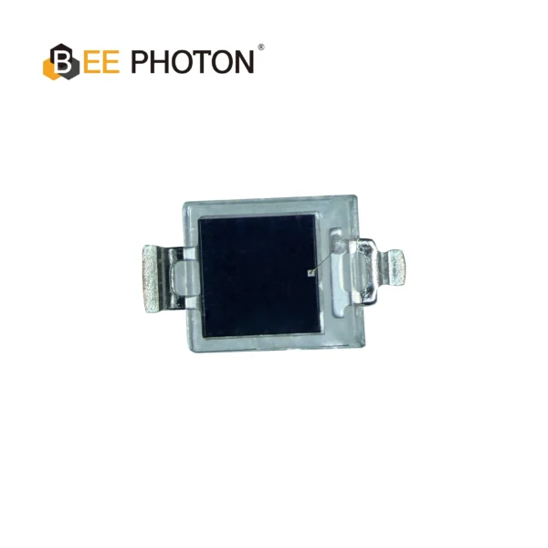
Before we get into the heavy math, let’s look at the physical realities. The PDCP08-501 is a surface-mount silicon PIN photodiode manufactured by BeePhoton.
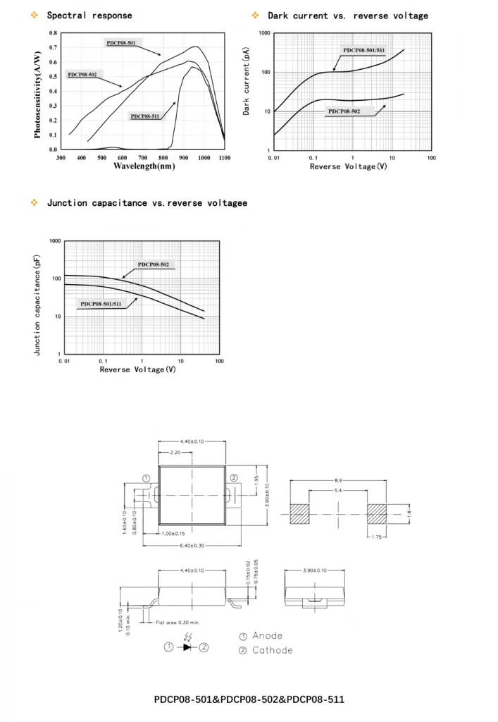
If you look at the mechanical drawing, the package is roughly 4.40mm by 3.90mm. But what actually matters is the photosensitive area. For the PDCP08-501, you get a 2.9mm x 2.9mm active area. This is a massive target. When you are dealing with free-space optics or trying to catch the beam of a slightly misaligned IR LED, having a near 3x3mm bucket to catch photons is a lifesaver. You don’t need sub-micron alignment tolerances on your assembly line, wich saves serious money in production.
The window material for the PDCP08-501 is an Epoxy resin (CR). Now, if you look at its sister part, the 511, that one uses a black epoxy (BK) to filter out visible daylight. But the PDCP08-501 is clear, meaning it sees a massive chunk of the spectrum.
Tearing Apart the Electro-Optical Specs
This is where datasheets usually get murky. We are going to look at the exact numbers provided for the PDCP08-501 and translate them into actual circuit design implications.
The Meat of It: Spectral Sensitivity
If your photodiode can’t see the light source, you just built a very expensive paperweight. The PDCP08-501 has a wide spectral response range from 450 nm all the way to 1100 nm.
If you look at the spectral sensitivity graph in the datasheet, you see a curve that starts low in the blue/green region (450nm) and climbs aggressively as it moves into the red and near-infrared (NIR). The peak sensitivity wavelength (lambda_p) hits right at 940 nm.
At 940 nm, the PDCP08-501 boasts a photosensitivity (S) of 0.7 A/W.
What does 0.7 A/W actually mean for your circuit? It means if you manage to hit the PDCP08-501 active area with exactly 1 Watt of 940nm optical power (please don’t, you’ll melt it, but mathematically speaking), the diode will generate 0.7 Amps of photocurrent.
In the real world, you are catching maybe 10 microwatts (10 uW) of optical power.
Photocurrent (I_pd) = 10 uW * 0.7 A/W = 7 microamps (7 uA).
That 7 uA is the signal your op-amp needs to amplify. Because the PDCP08-501 peaks at 940 nm, it is an absolute dream match for standard GaAs IR LEDs used in remote controls, optical switches, and light curtains. It also gives a respectable 0.2 A/W at 520 nm, so if you are using a green laser for some weird alignment rig, the PDCP08-501 will still see it.
The Silent Killer: Dark Current (Id)
Every photodiode leaks current, even in pitch black darkness. This is thermal generation of electron-hole pairs, and it’s called dark current. The PDCP08-501 specifies a typical dark current of 20 pA (max 1000 pA) when measured at a reverse voltage (Vr) of 10mV.
20 picoamps is very low. But here is the catch that trips up junior engineers: dark current scales with reverse bias and temperature.
If you look at the “Dark current vs. reverse voltage” graph for the PDCP08-501, you’ll notice that at 0.01V, Id is right around that 10-20 pA mark. But if you decide you want your PDCP08-501 to be super fast and you hit it with 10V of reverse bias, that dark current shoots up to roughly 100 pA.
Furthermore, the PDCP08-501 has a temperature coefficient of Id at 1.13 times/C. This means for every degree Celsius your board heats up, the dark current multiplies by 1.13. If your optical switch is sitting inside a hot factory enclosure running at 85C, your original 20 pA dark current is going to turn into a massive noise floor. You have to account for this DC offset in your TIA design, usually by AC-coupling the next stage or using an active servo loop to null out the DC baseline of the PDCP08-501.
Speed and Junction Capacitance (Cj)
Because the PDCP08-501 is a PIN photodiode, it has an intrinsic (I) layer sandwiched between the P and N layers. This thick depletion region physically separates the plates of the capacitor, drastically lowering the junction capacitance compared to a standard PN diode.
At Vr = 0V, the PDCP08-501 has a typical junction capacitance of 70 pF (measured at f=100kHz).
Why do we care about 70 pF? Because capacitance kills speed. When you hook the PDCP08-501 up to a transimpedance amplifier, that 70 pF forms a low-pass filter with your feedback resistor (Rf).
The datasheet gives a rise time (tr) of 0.15 microseconds (us) for the PDCP08-501 when tested at Vr=0V and a load resistance (Rl) of 1k Ohm.
Let’s check their math using the standard RC time constant formula:
tr approx = 2.2 * Rl * Cj
tr = 2.2 * 1000 Ohms * 70 x 10^-12 Farads
tr = 1.54 x 10^-7 seconds = 0.154 us.
Their datasheet is spot on. The PDCP08-501 isn’t lying to you. If you need it to be faster than 0.15 us, look at the third graph: “Junction capacitance vs. reverse voltage”. If you apply 10V of reverse bias to the PDCP08-501, the depletion region widens, and the capacitance drops dramatically. Lower capacitance means lower RC time constant, meaning a faster PDCP08-501. Just remember my warning about the dark current penalty!
Shunt Resistance (Rsh)
En PDCP08-501 has a typical shunt resistance of 0.5 Giga-Ohms (GOhm) at Vr=10mV.
Shunt resistance is basically the slope of the I-V curve right at 0V. A high Rsh is critical if you are operating the PDCP08-501 in photovoltaic mode (0V bias) because it dictates the Johnson noise (thermal noise) of the diode itself.
Formula for Johnson noise current:
Inoise = sqrt( (4 * k * T * BW) / Rsh )
Where k is Boltzmann’s constant, T is temp in Kelvin, BW is bandwidth.
Because the PDCP08-501 has a massive 0.5 GOhm typical shunt resistance, the thermal noise generated by the diode itself is practically nothing. Your op-amp’s voltage noise will likely dominate the system way before the PDCP08-501‘s thermal noise becomes an issue.
Potencia equivalente de ruido (NEP)
NEP is the Holy Grail spec for low-light detection. It tells you the minimum optical power required to achieve a signal-to-noise ratio of 1.
En PDCP08-501 boasts an NEP of 1.5 x 10^-14 W/Hz^(1/2).
Let’s say your system bandwidth is 10 kHz.
Total Noise Power = NEP * sqrt(Bandwidth)
Total Noise Power = 1.5 x 10^-14 * sqrt(10000)
Total Noise Power = 1.5 x 10^-14 * 100 = 1.5 x 10^-12 Watts.
This means if your incoming light signal is 1.5 pico-watts, the signal from the PDCP08-501 will be exactly equal to the noise floor. You definetly want your signal to be at least 10 times higher than this for reliable detection, so plan your emitter power accordingly. The fact that the PDCP08-501 can dig down into the low pico-watt range makes it incredibly robust for long-distance optical switches where the beam spreads out and gets weak.
Real-World App: Why Use the Beephoton PDCP08?
I want to share a recent scenario without naming the specific client. A company was building an industrial light curtain for machine guarding. They initially used a generic PN photodiode, but the ambient lighting in the factory (high-frequency LED bays) was causing massive false-trips. Furthermore, the vibration of the stamping press meant the IR beam from the transmitter was constantly dancing around the receiver surface.
We swapped them over to the PDCP08-501.
First, the 2.9×2.9mm large active area of the PDCP08-501 completely solved the vibration issue. The beam could dance around the surface by a millimeter in any direction, and the total captured power remained constant.
Second, because the PDCP08-501 has such high spectral sensitivity at 940nm, we were able to run their 940nm IR emitters at a much lower duty cycle, saving power and extending LED life.
We ran the PDCP08-501 into a simple CMOS op-amp configured as a transimpedance amplifier. Because we didn’t need MHz speeds for a light curtain (a few kHz is fine for human safety response times), we ran the PDCP08-501 at 0V bias. This kept the dark current near zero, and the 70pF capacitance of the PDCP08-501 was easily handled by throwing a small 2pF compensation capacitor across the feedback resistor of the TIA to prevent ringing. The system became bulletproof.
Fotodiodo Si PIN Serie PDCP08 PDCP08-501
Detección de alto rendimiento: El PDCP08-501 es un fotodiodo PIN de silicio de alta velocidad con ventana transparente.
Especificaciones: Con un área activa de 2,9×2,9 mm, este fotodiodo PIN ofrece una baja corriente oscura y una alta capacidad de respuesta, lo que lo convierte en un sensor ideal para interruptores ópticos generales y sistemas de detección de luz.
Let’s Look at the Environmental Survival
Datasheets aren’t just about optical purity; they are about surviving the real world.
The absolute maximum ratings for the PDCP08-501 show it can operate (Topr) between -40C and +100C.
-40C to +100C covers almost every automotive and harsh industrial requirement outside of directly bolting it to an exhaust manifold.
En PDCP08-501 also has an ESD rating of 1000V (Human Body Model). Now, 1000V might sound like a lot, but a human shuffling across a carpet can build up 5000V easily. While the PDCP08-501 is robust, you still need to use proper ESD grounding straps when handling these during manual board assembly. Don’t pull them out of the reel without grounding yourself, or you’ll degrade that beautiful 20pA dark current spec permanently.
Also, soldering. The PDCP08-501 handles a maximum soldering temperature (Tsol) of 260C for 3 seconds. If you are hand-soldering prototypes, do not linger on the pads. Get in with the iron, reflow the solder, and get out. If you bake the epoxy lens of the PDCP08-501 for too long, you will cause thermal stress micro-fractures which ruin the optical clarity and alter the directivity angle (which is natively +/- 65 degrees for the PDCP08-501).
The Specs That Actually Matter
Here is a quick cheat sheet for the PDCP08-501 when you are mocking up your spice models.
| Parámetro | Símbolo | PDCP08-501 Value | Why you should care |
|---|---|---|---|
| Área activa | Area | 2.9 x 2.9 mm | Bigger is easier to align physically. |
| Longitud de onda pico | lambda_p | 940 nm | Match your LED to this exact number for max efficiency. |
| Fotosensibilidad | S | 0.7 A/W (@940nm) | Determines your raw signal current. |
| Corriente oscura | Id | 20 pA (typ) | Your baseline DC noise floor at low bias. |
| Junction Cap | Cj | 70 pF (typ) | Dictates the bandwidth of your TIA op-amp circuit. |
| Tiempo de subida | tr | 0.15 us | The fastest pulse the PDCP08-501 can cleanly output at 0V. |
| Shunt Resistance | Rsh | 0.5 GOhm | Prevents the diode from generating its own thermal noise. |
Designing the Transimpedance Amplifier (TIA) for the PDCP08-501
Since we are deep in the weeds, let’s talk about the circuit. The most common mistake I see is engineers hooking the PDCP08-501 up to a standard voltage amplifier. Don’t do that. Photodiodes are current sources. You need a current-to-voltage converter (TIA).
You connect the anode of the PDCP08-501 to the inverting input (-) of your op-amp, and the cathode to ground (for photovoltaic mode). The non-inverting input (+) goes to ground. You place a feedback resistor (Rf) between the op-amp output and the inverting input.
The output voltage is simple:
Vout = I_pd * Rf
Si el PDCP08-501 is generating 1 microamp of current from an IR beam, and you use a 1 Mega-Ohm Rf:
Vout = 1 uA * 1,000,000 Ohms = 1 Volt.
But here is where the PDCP08-501‘s 70pF capacitance (Cj) fights you. That Cj sits directly across the op-amp inputs. It creates a pole in the noise gain of the amplifier, which will cause your op-amp to oscillate and output a massive sine wave instead of your signal.
To fix this with the PDCP08-501, you must calculate a feedback capacitor (Cf) to put in parallel with your Rf.
The text-book formula for ideal stability is:
Cf = sqrt( C_total / (2 * pi * Rf * GBW) )
Where C_total is the PDCP08-501 capacitance (70pF) plus the op-amp input capacitance (usually ~5pF), and GBW is the gain-bandwidth product of your chosen op-amp.
Because the PDCP08-501 has a relatively low 70pF for its large physical size, Cf usually ends up being around 1pF to 3pF. This small compensation capacitor ensures your PDCP08-501 outputs crisp, clean square waves when the optical beam is broken.
Fotodiodo Si PIN Serie PDCP08 PDCP08-502
El PDCP08-502 es un fotodiodo PIN de silicio de 2,9×2,8 mm de alta respuesta diseñado para aplicaciones fotoeléctricas de precisión. Con baja capacitancia de unión, baja corriente oscura y un amplio rango espectral (340-1100 nm), es el componente ideal para interruptores ópticos y módulos de detección compactos que requieren una salida de señal estable y rápida.
FAQ: Rapid Fire PDCP08-501 Questions
Can I use the PDCP08-501 to detect visible light?
Yes, absolutely. While the PDCP08-501 peaks at 940nm (IR), the spectral sensitivity curve shows it is highly responsive all the way down to 450nm. It works great with red (650nm) and green (520nm) lasers. If you only want IR and want to block visible light, you should look at the PDCP08-511 instead, which has a black daylight filter.
Why does my PDCP08-501 circuit have so much noise when it gets hot?
Remember the temperature coefficient of 1.13 times/C. If your board gets hot, the dark current of the PDCP08-501 rises exponentially. If you have a massive feedback resistor (like 10 Meg-Ohms), that dark current turns into a huge DC voltage offset. At high temps, try reducing your reverse bias voltage to 0V to crush the dark current back down.
Is the PDCP08-501 fast enough for fiber optic data communication?
No. The PDCP08-501 has a rise time of 0.15us (150 nanoseconds). That gives you a bandwidth in the low Megahertz range. It is perfect for optical switches, light curtains, encoders, and remote controls. Fiber optic data running at Gigabits per second requires much smaller InGaAs photodiodes with capacitances in the sub-1pF range. The PDCP08-501 is built for robustness and light capture area, not gigahertz speed.
Time to Build Something Cool?
Hopefully, this deep dive saved you a few hours of head-scratching. Stop fighting with inferior generic diodes that drift all over the place when the temperature changes. The PDCP08-501 provides a massive 2.9×2.9mm capture area, ultra-low 20pA dark current, and the reliability you need for industrial designs.
If you are ready to stop breadboarding and start moving to production, you need the right parts in your hands. You can grab the exact specifications and explore the PDCP08-501 here.
Got a weird edge-case application? Trying to figure out if the PDCP08-501 will survive your specific environmental chamber? Don’t just guess. Reach out to the engineers who actually build these things. Head over to the BeePhoton Contact Us page or shoot an email directly to info@photo-detector.com. We love talking circuit design, and we can get you the samples you need to make your next prototype work on the first spin.