There is nothing—and I mean nothing—more frustrating for an IoT designer than a battery that dies three months into a “five-year” deployment. You calculate the power budget, you select the best MCU, you put everything to sleep, and yet, the device drains.
Why? Often, it’s the eyes of the device that are too hungry.
If you are designing IoT sensor nodes, specifically those involving IoT optical sensors, the choice of your light detection component is critical. I’ve spent over a decade messing around with optics, and I’ve seen too many brilliant Smart Home or Industrial IoT (IIoT) designs fail because the engineer treated the photodiode as an afterthought.
Today, we are diving deep into the world of the low power photodiode. We aren’t just looking at datasheets; we’re looking at how to actually integrate these things into battery operated sensors without killing your energy budget.
The Power Budget Struggle is Real
When we talk about IoT, we are usually talking about devices running on coin cells (like a CR2032) or maybe a couple of AA batteries. You have a finite amount of juice—let’s say 220 mAh for a coin cell.
If your device draws even a few extra micro-amps (uA) while in standby, you are shaving years off the product’s lifespan.
Here is the kicker: Optical sensors often need to be “always on” or at least “always aware” to wake up the main system. If you are building a smoke detector, a flame sensor, or a pulse oximeter, you can’t just turn the sensor off completely. It needs to be watching.
This is where the specific characteristics of a low power photodiode come into play. It’s not just about the active current; it’s about the leakage.

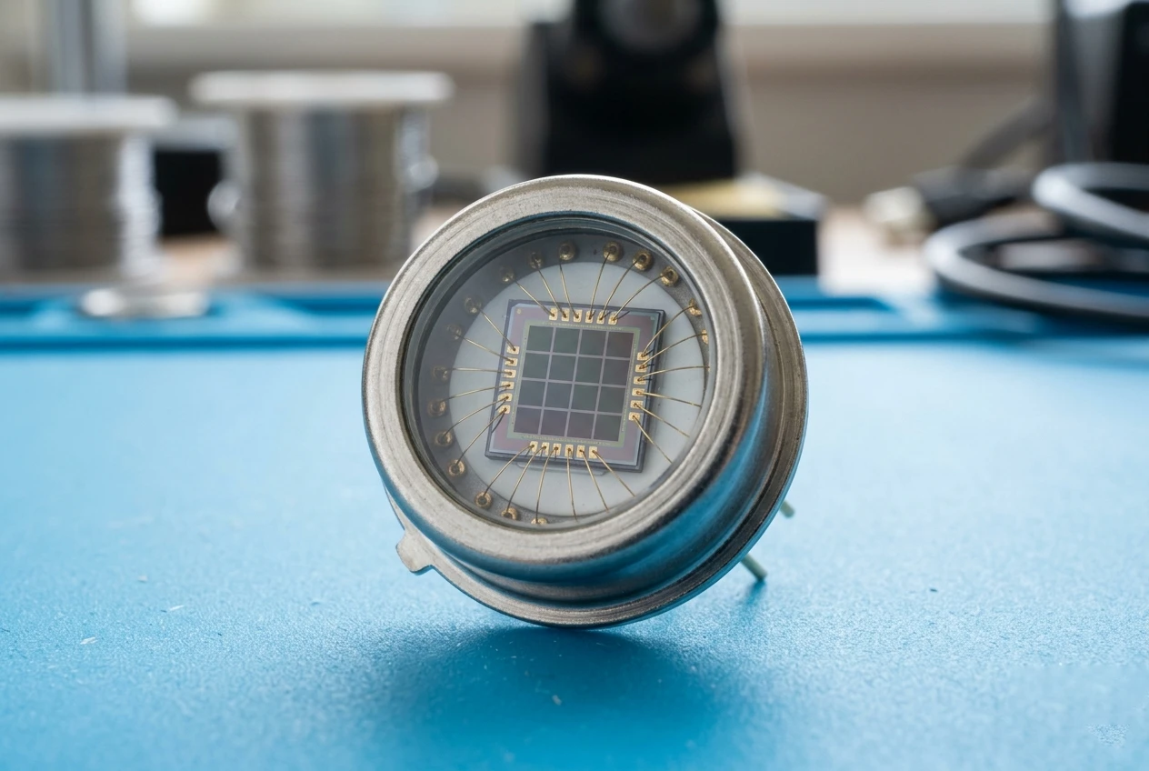
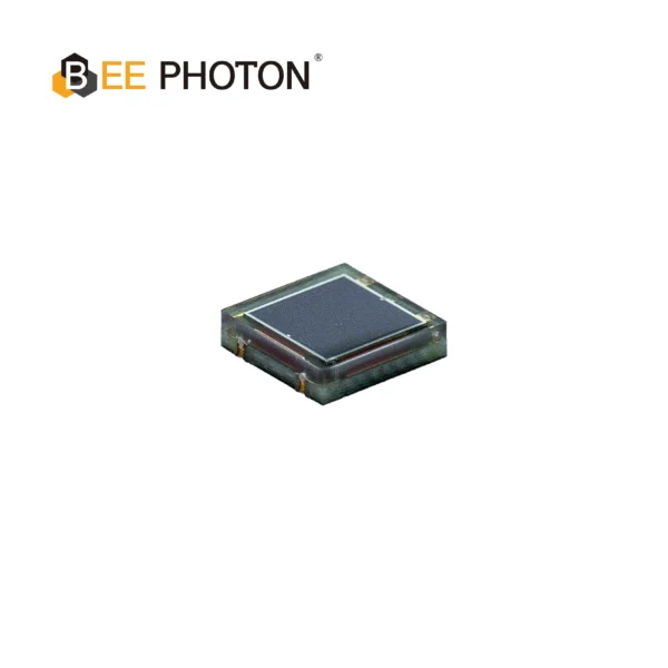
Si PIN Photodiode with UV sensitivity enchanced (320-1060nm) PDCC100-701
Our High Responsivity Si PIN Photodiode offers a superior signal for demanding applications. It excels in low-light UV detection from 320-1060nm.
Understanding the “Leakage”: Dark Current (Id)
If you take one thing away from this article, let it be this: Dark Current is the enemy of battery life.
In technical terms, Dark Current (labeled as I_d or I_dark in datasheets) is the current that flows through the photodiode even when there is absolutely no light hitting it.
When you bias a photodiode (apply voltage to it) to make it faster or more responsive, you inadvertently create a path for leakage current. For a standard industrial diode, this might be 1 nA (nano-amp) or even 10 nA.
“10 nA is nothing,” you might say.
Sure, in a plugged-in device, it’s noise. But in ultra-low-power IoT sensor nodes, that leakage adds up, especially as temperature rises.
The Temperature Trap
Here is a controversial opinion: Most datasheet specs regarding Dark Current are borderline useless.
Why? because they are measured at 25 degrees Celsius (room temp). But if you stick your IoT optical sensors in an outdoor enclosure in Arizona, that temperature hits 60 or 70 degrees Celsius.
Rule of Thumb: Dark current roughly doubles for every 10 degrees Celsius increase in temperature.
So, your “low power” 1 nA leakage at 25C becomes:
- 35C: 2 nA
- 45C: 4 nA
- 55C: 8 nA
- 65C: 16 nA
Suddenly, your low power photodiode isn’t looking so low power anymore. This parasitic drain can destabilize high-impedance amplifier circuits, causing the system to wake up falsely. False wake-ups = dead batteries.
Photovoltaic Mode vs. Photoconductive Mode
If you are obsessed with saving power (and you should be), you need to look at how you are driving the low power photodiode.
There are two main modes of operation:
- Photoconductive Mode (Reverse Bias): You apply a reverse voltage (Vr) across the diode.
- Pros: Faster response time, lower capacitance (better bandwidth).
- Cons: High Dark Current (I_d). The battery is constantly pushing against the diode’s resistance.
- Photovoltaic Mode (Zero Bias): No external voltage is applied. The diode acts like a tiny solar cell.
- Pros: Zero Dark Current. Noise is limited only by the thermal noise of the shunt resistance.
- Cons: Slower response time (higher junction capacitance).
For 90% of battery operated sensors where you are measuring light intensity (lux meters, smoke detection, ambient light sensing), Photovoltaic Mode (Zero Bias) is the absolute winner.
A Quick Comparison
I put together this table to help you visualize the trade-offs when selecting a low power photodiode configuration.
| Feature | Photovoltaic Mode (Zero Bias) | Photoconductive Mode (Reverse Bias) |
|---|---|---|
| Power Consumption | Lowest (Ideal for IoT) | Higher (Due to leakage current) |
| Dark Current | Negligible | Increases with Voltage & Temp |
| Speed/Bandwidth | Slower (High Capacitance) | Faster (Low Capacitance) |
| Linearity | Excellent | Good |
| Circuit Complexity | Simple | Moderate |
If you are designing IoT sensor nodes that wake up once a second to check light levels, go with Zero Bias.

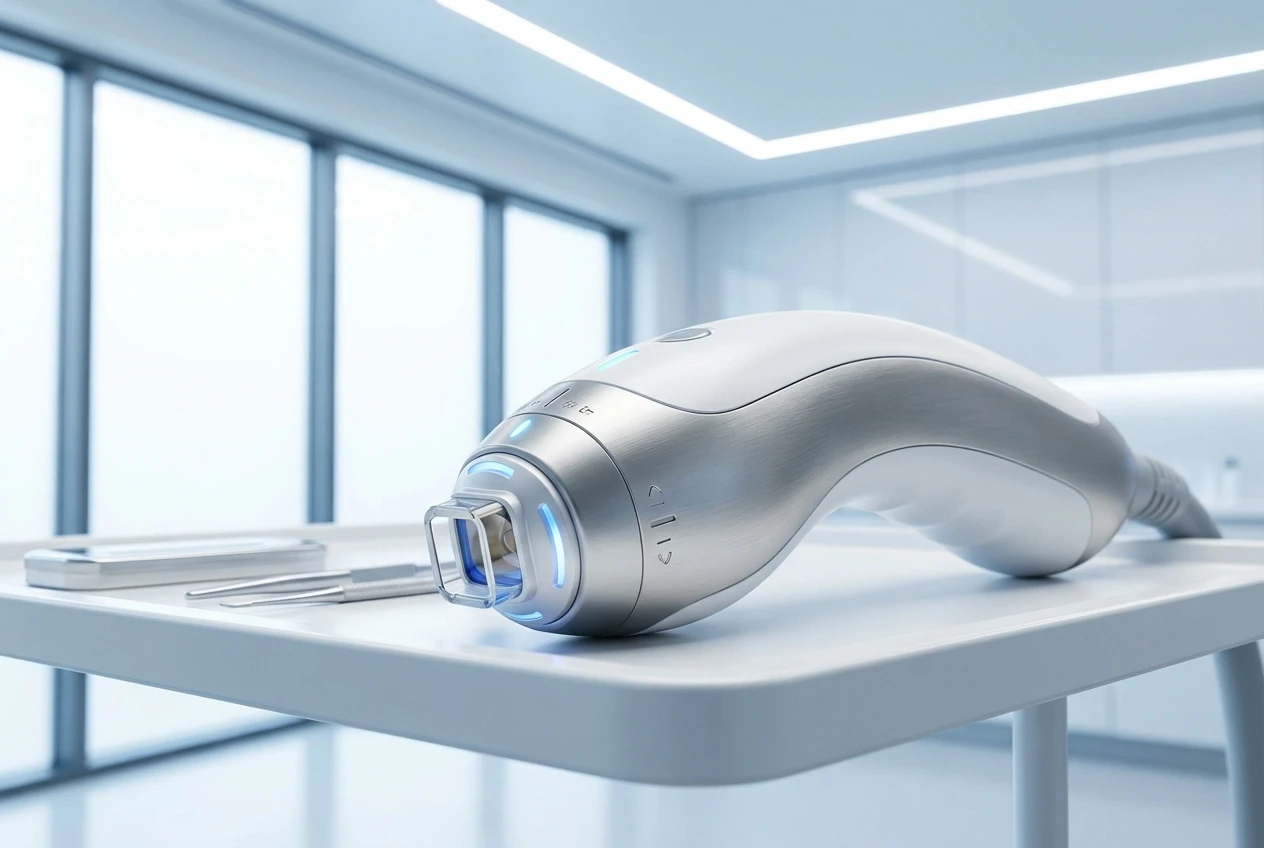
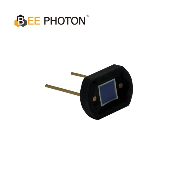
Si PIN Photodiode with UV sensitivity enchanced (320-1060nm) PDCT16-601
Our Borosilicate Window Photodiode ensures superior UV to NIR detection. This photodiode with a durable borosilicate window excels in spectroscopy & medical analysis.
Selecting the Right Component: Si PIN Photodiodes
Silicon (Si) PIN photodiodes are the workhorses of the IoT world. They are cheap, reliable, and cover the visible to near-infrared spectrum (300nm to 1100nm).
At BeePhoton, we specialize in these optics. Our Si PIN photodiodes are specifically processed to minimize impurities, which naturally keeps the shunt resistance (R_sh) high and dark current low.
What is Shunt Resistance (R_sh) and Why Do I Care?
In a low power photodiode, Shunt Resistance is basically the resistance of the diode junction when it’s not biased.
The Formula:V_out = I_photo * R_feedback
However, noise is generated by the thermal agitation in the equivalent resistance.Noise Current (I_n) = SquareRoot(4 * k * T * Bandwidth / R_sh)
- k = Boltzmann constant
- T = Temperature
Look at the formula. R_sh is in the denominator. This means Higher Shunt Resistance = Lower Noise.
For battery operated sensors, a high R_sh allows you to use larger feedback resistors in your amplifier without being swamped by noise. This means you get more gain (sensitivity) for “free” without needing power-hungry active gain stages.
Design Tips for Low Power IoT Optical Sensors
Okay, let’s get into the weeds. You have your low power photodiode, but how do you design the rest of the circuit?
1. Pulse Your LEDs
If your system involves an emitter (like in a particle monitor or optical switch), never run the LED continuously. Pulse it.
Drive the LED for 10 microseconds, take the reading from the low power photodiode, and go back to sleep. This reduces the duty cycle to maybe 0.01%, saving massive amounts of power.
2. Choose the Right Op-Amp
Don’t pair a premium low power photodiode with a trashy Op-Amp. You need an Op-Amp with:
- Extremely low input bias current (pico-amps or femto-amps).
- Low quiescent current (I_q). Some modern Op-Amps run on < 1 uA.
3. Guard Rings are Not Optional
Since we are dealing with tiny currents (nA or pA range) from the low power photodiode, surface leakage on the PCB can ruin your day. Finger oils or humidity on the PCB can create a conductive path that bypasses your sensor.
Use a guard ring trace around the photodiode inputs connected to the same potential as the inputs. This prevents leakage currents from flowing into your measurement node.
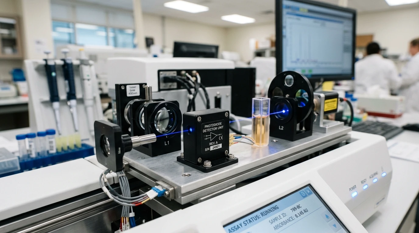
Si PIN Photodiode with NIR sensitivity enchanced (350-1100nm) PDCC34-501
Bee Photon offers a High Stability PIN Photodiode for precise industrial sensing. This NIR enhanced photodiode ensures reliable measurements from 350-1100nm. A top choice for a high stability photodiode.
Real World Case Study: The Smart Ag Monitor
I want to share a story (anonymous, of course) about a project we helped with. A client was building a soil health monitor for smart agriculture. It used IoT optical sensors to measure leaf color (chlorophyll levels) using reflectance.
The Problem:
The device used a standard off-the-shelf photodiode in reverse bias. The batteries were supposed to last 2 years. They were dying in 4 months. The culprit? The device sat in direct sunlight. The internal temp hit 70C. The dark current on their generic diode spiked to 50 nA, draining the battery even when the device was “sleeping.”
The Solution:
We switched them to a high-quality low power photodiode from our BeePhoton BP-series and redesigned the circuit to Zero Bias operation.
- Eliminated the bias voltage (saved power).
- The high Shunt Resistance of our diode allowed them to maintain sensitivity without the noise floor creeping up.
- We implemented an interrupt-driven wake-up only when a significant light change occurred.
The Result:
Field battery life extended to 2.5 years. The client was ecstatic, and we saved a ton of e-waste from dead batteries.
Integrating with BeePhoton
If you are scrolling through Mouser or DigiKey, you might find thousands of options. But generic diodes often lack the batch-to-batch consistency required for precision IoT sensor nodes.
At BeePhoton, we ensure that every low power photodiode we ship meets strict dark current and capacitance specs. We know that in B2B applications, reliability is currency.
You can check out our main site at https://photo-detector.com/ to see the full range.
Also, if you are stuck on a schematic and don’t know why your transimpedance amplifier is oscillating, just ask us. We actually like solving these problems.
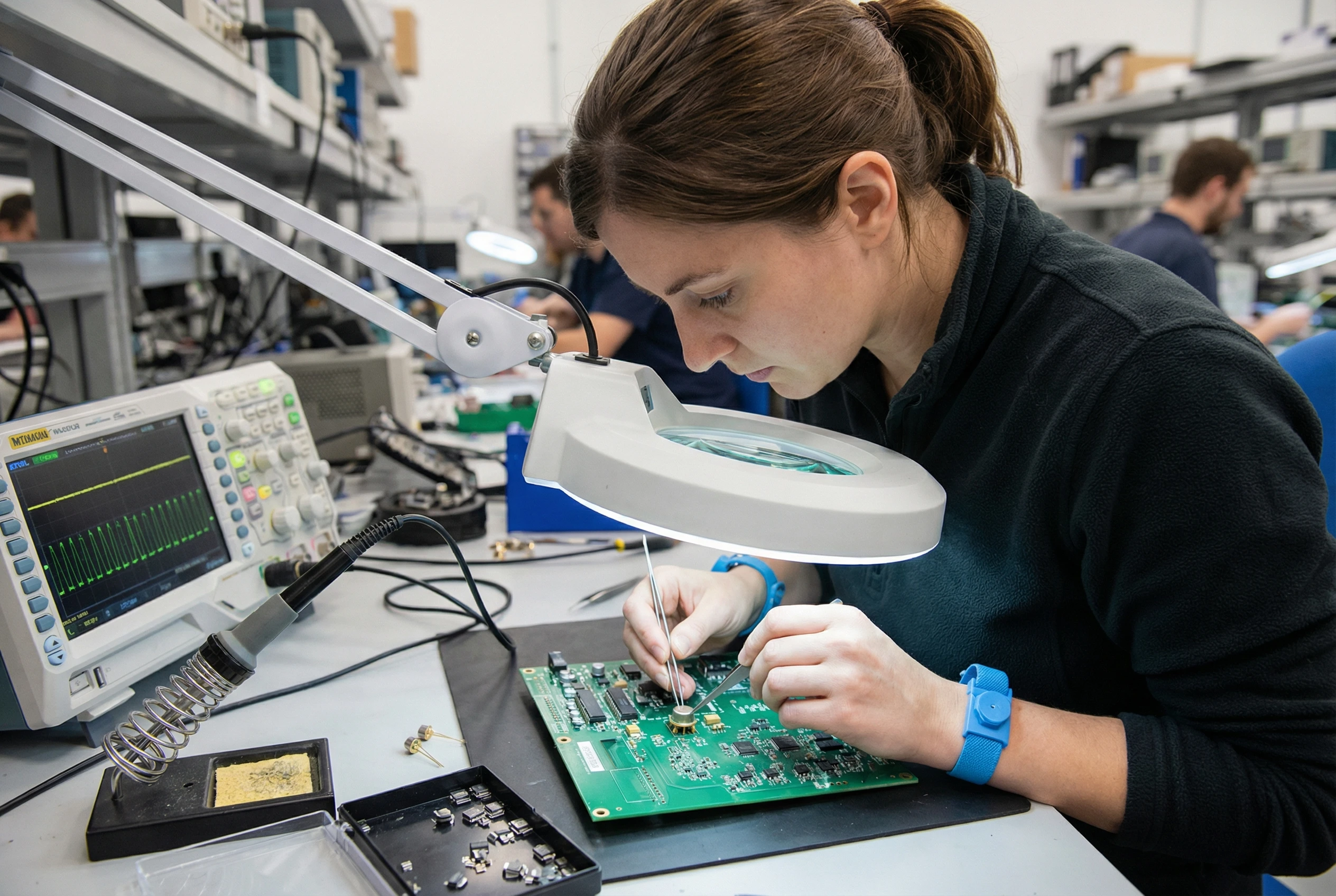
Si PIN Photodiode with low dark current (350-1060nm) PDCD07-001
Experience superior performance with our High Speed Si PIN Photodiode. Offering low dark current and a wide 350-1060nm spectral range, it ensures reliable and fast data transmission. This DIP-packaged high speed Si PIN Photodiode is your ideal choice for high-bandwidth optical communication systems.
FAQ: Common Questions about Low Power Photodiodes
1. Can I use a regular photodiode for battery-operated devices?
Technically, yes. But a “regular” photodiode might have a lower shunt resistance. This means you have to pump more amplification into the signal to read it, which brings up the noise floor. A dedicated low power photodiode is optimized for high shunt resistance, giving you a cleaner signal with less power.
2. How does the active area size affect power consumption?
This is a trade-off. A larger active area captures more light (good signal), but it also has higher junction capacitance (slower) and generally higher dark current (more leakage). For IoT sensor nodes requiring ultra-low power, we usually recommend the smallest active area that can still capture your beam, unless you are in zero-bias mode where leakage is less of a factor.
3. What is the difference between a phototransistor and a low power photodiode?
Great question. A phototransistor has high gain built-in (it amplifies the current). It sounds great, but they are slow and have very poor linearity. Plus, their temperature stability is terrible. For precision IoT optical sensors, a low power photodiode is far superior in terms of accuracy and temperature stability.
4. Does BeePhoton offer custom photodiodes?
Yes, we do. Sometimes standard packaging doesn’t fit your sleek IoT enclosure. We can customize the pigtail, the connector, or even the spectral response filter.
Wrapping Up
Designing battery operated sensors is an art of compromise. You trade speed for power, gain for noise, and cost for reliability. But the one thing you shouldn’t compromise on is the quality of your input sensor.
The low power photodiode is the heart of your optical system. Treat it with respect, design your circuit around its strengths (Zero Bias!), and your batteries will thank you.
If you are currently designing a device and hitting a wall with power consumption, let’s talk. We have helped countless engineers optimize their IoT optical sensors for the real world.
Ready to optimize your sensor design?
- Explore our products: Si PIN photodiodes
- Need technical advice? Contact Us
- Email the engineering team: info@photo-detector.com
Don’t let a leaky diode drain your project’s success. Choose BeePhoton.