Robotics and automation control used to be a lot simpler. You just needed to get a load from point A to point B without crashing into a wall. But today? If your servo motor is off by even a fraction of a degree, you’ve got a scrapped part or a completely jammed assembly line.
I’ve been working around automation control and motor feedback sensors for years, and it always blows my mind how many engineers cheap out on the very components that tell their system where it actually is. You can have the most expensive servo drive in the world, but if your motor feedback sensors are feeding it garbage data, your system is gonna run like garbage.
Let’s get one thing straight right out of the gate. There’s a huge debate in the industry right now about magnetic versus optical setups. A lot of folks will tell you that magnetic encoders are the future cause they handle dirt and heavy vibration well. Honestly? I think magnetic motor feedback sensors are massively overrated if you’re building a truly high-precision robotic joint. Sure, they’re rugged, but when sub-millimeter positioning is on the line, you just cant beat the pure, unadulterated accuracy of an optical encoder module.
In this guide, I’m gonna break down exactly how to spec out your motor feedback sensors, the dirty math behind resolution, and why upgrading your automation control hardware is the easiest cheat code for better machine performance.
The Real Role of Motor Feedback Sensors in Automation Control
To understand why this stuff matters, you have to look at how automation control actually functions. A servo motor doesn’t just spin blindly. It relies on a closed-loop system. The controller sends a command to move, the motor moves, and then the motor feedback sensors report back exactly how far it actually went.
If there’s a difference between the commanded position and the actual position, the controller adjusts the current to fix it. This continuous loop happens thousands of times a second. But here’s the kicker: the controller only knows what the motor feedback sensors tell it. If your motor feedback sensors have lag, low resolution, or are picking up electrical noise, the controller will make incorrect adjustments. This leads to jitter, overheating, and sloppy automation control.
When you’re manufacturing robotic joint modules, your clients expect a repeatability specification at the sub-millimeter level. You simply cannot achieve that with bottom-tier motor feedback sensors. You need components that offer high speed, incredible resolution, and rock-solid reliability.
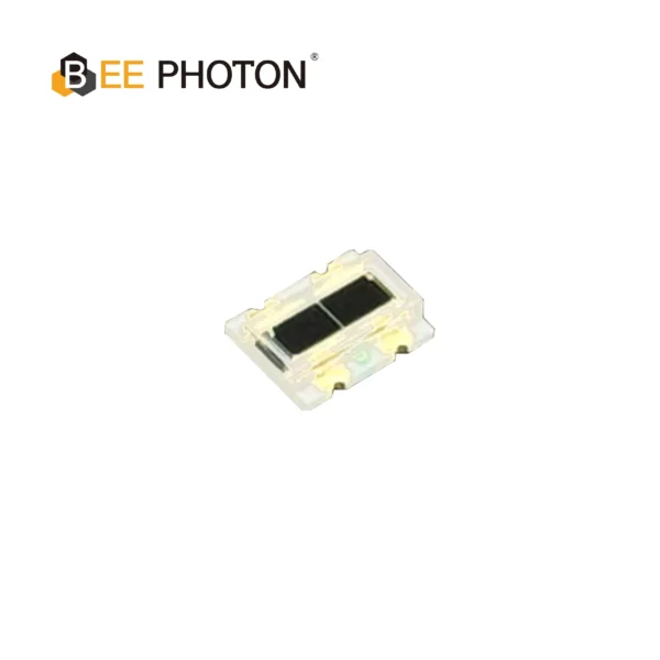
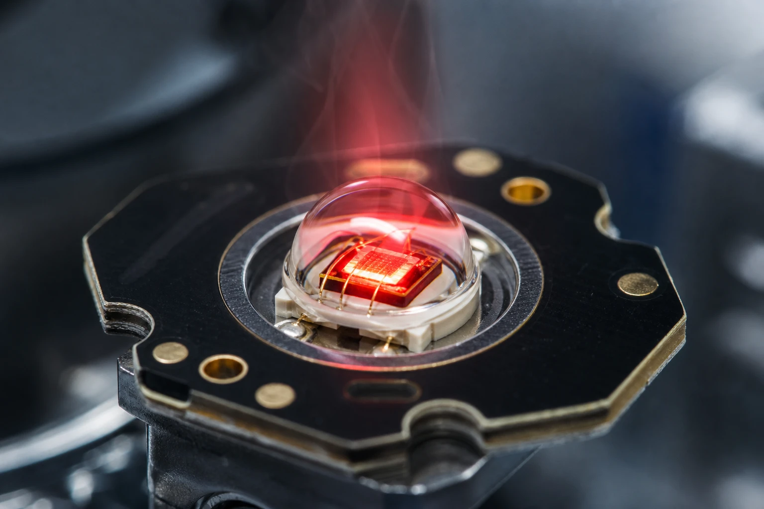
Si PIN Photodiode Array PDCA02-102
The PDCA02-102 is a high-performance Si PIN Photodiode Array designed for precision optical measurement and alignment systems. Engineered by Bee Photon, this 2-segment photodiode delivers a wide spectral response range from 400nm to 1100nm, covering the entire visible light spectrum into the near-infrared (NIR) region.
With its compact COB (Chip on Board) package and resin window, the PDCA02-102 ensures durability and easy integration into compact optical modules. It is specifically optimized for industrial applications where high sensitivity and fast response times are critical.
Why an Optical Encoder Module Wins for Precision
So why do I push so hard for optical motor feedback sensors over magnetic ones? It comes down to physics.
Inside an optical encoder module, you have an LED light source, a transparent disk with tiny opaque lines printed on it (the code wheel), and a receiver on the other side. As the motor shaft spins, the disk spins with it. The lines interrupt the light beam. The receiver catches these flashes of light and turns them into electrical pulses.
Because we can print those lines microscopically close together using photolithography, an optical encoder module can achieve insanely high native resolutions. I’m talking upwards of 10,000 Pulses Per Revolution (PPR) right out of the box, without any digital tricks. Magnetic motor feedback sensors rely on sensing the changing poles of a magnet, which is fine, but the physical limits of magnetizing a disc mean you naturally hit a wall when trying to scale up the resolution.
The secret sauce in any high-end optical encoder module is the receiver. If the receiver is slow, the whole system bottlenecks. That’s why at BeePhoton, we integrate our ultra-fast Si PIN photodiodes into these systems. These specific photodiodes have the raw bandwidth needed to catch high-speed light pulses without dropping counts, even when the motor is screaming at 5000 RPM in a demanding automation control enviroment.
The Math Behind Motor Feedback Sensors (No Ph.D. Required)
Alot of engineers get intimidated by the math used to spec out motor feedback sensors, but it’s really just basic algebra. You just need to match your mechanical speed with your electrical bandwidth.
1. Calculating Maximum Encoder Resolution
For incremental motor feedback sensors, the internal electronics have a maximum frequency response. This is the absolute speed limit at which the sensor can process light pulses. If you spin the motor too fast, the optical encoder module will overwork its processor, degrade the signal, and you’ll end up with cumulative positioning errors.
Here is the golden formula to make sure your motor feedback sensors won’t bottleneck your automation control system:
Max encoder resolution (PPR) = (Operating Frequency * 60) / Max RPM
Let’s do a real world example. Say you have an optical encoder module with a frequency response of 100 kHz (which is 100,000 Hz) and your servo motor needs to hit a mechanical speed of 3,000 RPM.
Max Resolution = (100,000 * 60) / 3,000
Max Resolution = 6,000,000 / 3,000 = 2,000 PPR.
If you try to slap a 2500 PPR disk into that specific setup, your motor feedback sensors will electrically max out at 2400 RPM. The motor will keep spinning to 3000 RPM, but the automation control system will be totally blind for that top 600 RPM. Always run this math before buying motor feedback sensors.
2. Resolution Multiplication (The X4 Cheat Code)
If your standard motor feedback sensors don’t have enough native resolution for your robotic joint, you dont necessarily need to buy a more expensive optical encoder module. You can use resolution multiplication through your PLC or drive.
Most incremental motor feedback sensors output two signals: Channel A and Channel B. These are shifted by 90 electrical degrees (this is called quadrature).
- If your automation control drive only counts the rising edge of Channel A, that’s X1 encoding.
- If it counts the rising and falling edges of Channel A, that’s X2 encoding (doubling your resolution).
- If it counts the rising and falling edges of BOTH Channel A and Channel B, that’s X4 encoding.
So, if you buy standard motor feedback sensors with a native 1,000 PPR, using X4 encoding instantly gives your automation control system 4,000 pulses per revolution to work with.
3. Encoder Accuracy Formula
Keep in mind, resolution is just how many slices the pie is cut into. Accuracy is whether those slices are actually the right size. The accuracy of your motor feedback sensors is calculated simply by:
Encoder Accuracy = | Actual Mechanical Position – Reported Sensor Position |
Even the best optical encoder module will have slight errors. Mechanical misalignment is the biggest killer here. If your motor feedback sensors are mounted with an angular deviation of more than ±0.5 degrees, you’ll introduce a sinusoidal position error that ruins your automation control precision.
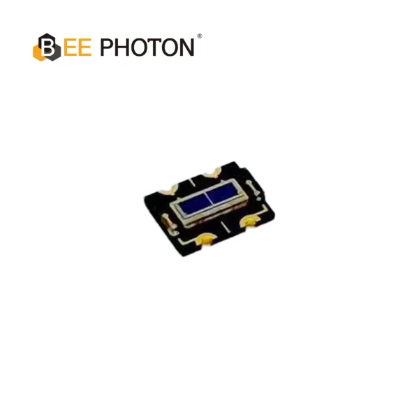
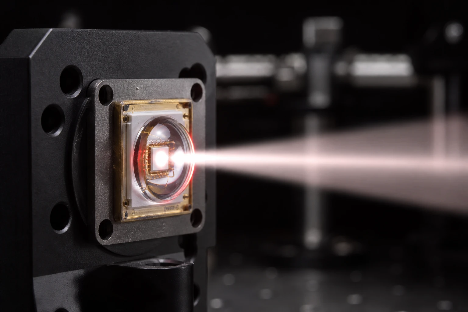
Si PIN Photodiode Array PDCA02-601
The Bee Photon PDCA Series is a precision-engineered Dual PIN Photodiode designed for high-end industrial sensing. Unlike standard single-element detectors, this silicon-based device features a segmented array structure (PD A and PD B), making it the perfect solution for differential sensing and background suppression optical switches. With a wide spectral response from 350nm to 1060nm, it ensures versatile performance across visible and near-infrared wavelengths.
Dealing with Noise and Misalignment in Motor Feedback Sensors
I’ve seen it a hundred times on the factory floor. A company drops big money on premium motor feedback sensors, bolts them onto the servo, and then wonders why the automation control system is throwing fault codes.
Mounting Tolerance:
When installing an optical encoder module, achieving a mounting accuracy of ±0.05 mm is absolutely critical. If the disc isn’t perfectly concentric with the motor shaft, the light from the LED won’t hit the Si PIN photodiodes perfectly. This creates a wobbly signal. Your motor feedback sensors will report that the motor is speeding up and slowing down during a single rotation, even if it’s spinning at a perfectly constant speed.
Electromagnetic Interference (EMI):
Motor feedback sensors are usually sitting right next to massive, noisy power cables feeding the servo motor. This EMI can induce false pulses in the sensor cables. To fight this, always use shielded, twisted-pair cables for your motor feedback sensors. Ground the shield at the automation control panel end only, not at the sensor end, to avoid ground loops.
Real World Case Study: Fixing Jitter in a Holonomic Robot
Let me share an anonymous story from a client we worked with recently. They manufacture centimeter-sized holonomic inchworm robots for semiconductor inspection. Because these robots operate in microscopically tight spaces, their automation control needs are insane.
Originally, they were using off-the-shelf magnetic motor feedback sensors. But during testing, the robots had a terrible “jitter” when trying to hold a static position. The magnetic fields from the different axes were actually causing crosstalk. The motor feedback sensors on the X-axis were picking up magnetic noise from the Y-axis motor.
They reached out to us, and we realized they needed to completely ditch the magnetic setup. We helped them transition to a custom optical encoder module setup for all four axes. By using an integrated 2-DOF scale and outfitting the receivers with our high-speed Si PIN photodiodes, we entirely eliminated the magnetic crosstalk.
The result? The new motor feedback sensors provided a measurement resolution of 0.1 micrometers in the static state, and the automation control jitter completely vanished. They were able to achieve sub-micrometer positioning without any of the headache. That’s the power of choosing the right motor feedback sensors.
Comparing Motor Feedback Sensors for Automation Control
If you’re still on the fence about which motor feedback sensors to spec for your next project, here is a quick breakdown.
| Feature / Type | Optical Encoder Module | Magnetic Encoders | Resolvers |
|---|---|---|---|
| Primary Use Case | High-precision robotics, CNC, precise automation control | Dirty, high-vibration environments, basic AGVs | Extreme temperatures, heavy industrial machinery |
| Max Resolution | Extremely High (Often > 10,000 PPR native) | Medium (Usually < 2048 PPR native) | Low to Medium |
| Accuracy | Excellent (sub-millimeter positioning) | Good | Moderate |
| Susceptibility to Dirt | High (Requires sealed IP67 housing) | Low | Very Low |
| Signal Speed / Response | Ultra-fast (Especially with Si PIN photodiodes) | Moderate | Slow (Requires analog to digital conversion) |
As you can see, if automation control precision is your main goal, an optical encoder module is the clear winner for your motor feedback sensors.
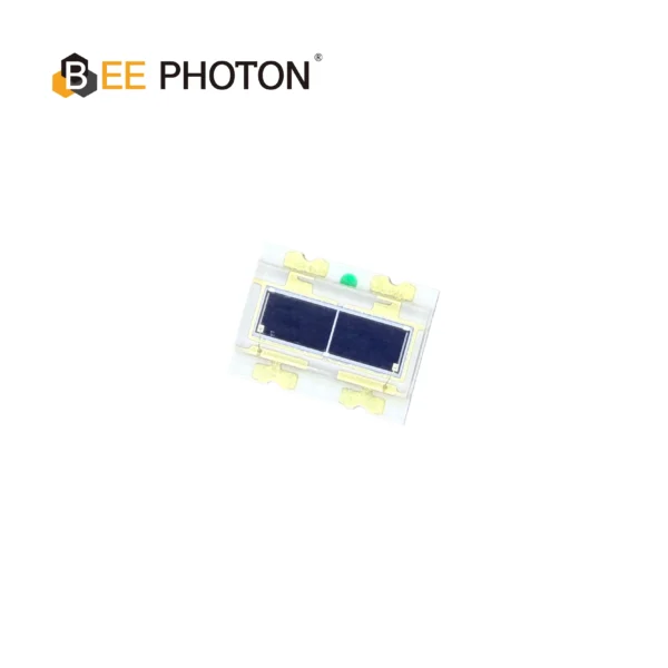
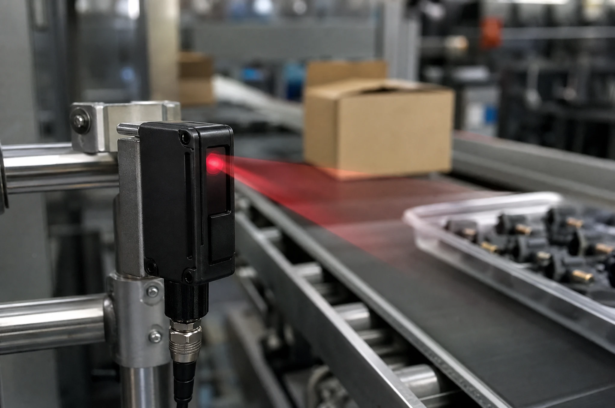
Si PIN Photodiode Array PDCA02-602
The Bee Photon PDCA Series is engineered specifically as a Background Suppression Photodiode to solve complex detection challenges in industrial environments. By utilizing a high-precision two-segment architecture (PD A and PD B), this device allows for differential signal processing, effectively filtering out background interference. It is the premier choice for manufacturers designing reliable background suppression optical switches and proximity sensors.
FAQ: Everything Else You Need to Know About Motor Feedback Sensors
1. What happens if my motor feedback sensors don’t have enough resolution?
If your motor feedback sensors have insufficient resolution, they won’t provide enough data points to the automation control system. The controller will essentially be “guessing” the position between pulses. This leads to rough motor operation, audible noise (whining), and poor positioning accuracy.
2. Can I use an optical encoder module in a dusty factory enviroment?
Yes, definetly. While the internal optical components are sensitive to dust, modern industrial motor feedback sensors are built with heavy-duty enclosures. Just make sure the optical encoder module you purchase has an IP67 rating, which means it is completely dust-tight and can even withstand temporary immersion in water.
3. Why are my motor feedback sensors losing counts over time?
Losing counts is almost always an electrical issue, not a mechanical one. It usually means your motor feedback sensors are experiencing electromagnetic interference (EMI) that is either adding false pulses or swallowing real ones. Check your cable shielding, ensure your automation control grounds are solid, and verify that your operating frequency isn’t exceeding the max bandwidth of the optical encoder module.
Upgrade Your Automation Control Today
Look, you can spend months tweaking the PID loops in your automation control software, but if you’re feeding the system bad data, you’re just fighting a losing battle. The foundation of any reliable, high-precision robotic system is the physical hardware measuring the movement.
By upgrading to premium motor feedback sensors—specifically a high-resolution optical encoder module—you instantly give your controllers the crisp, clean, high-speed data they need to perform flawlessly. And when it comes to capturing those light signals with zero lag, nothing beats the performance of dedicated optical components.
If you’re tired of dealing with jitter, lost counts, or subpar automation control, it’s time to upgrade your motor feedback sensors. At BeePhoton, we specialize in the optical receiver tech that makes these systems tick. Whether you need bare components or want to discuss how our tech can integrate into your custom motor feedback sensors, we’re here to help.
Don’t let bad sensor data ruin a great machine design. Head over to our contact us page today, or shoot us an email directly at info@photo-detector.com to request a quote and see how we can level up your automation control systems.