If you build enviromental monitoring gear for a living, you already know the headache of getting stable, repeatable low-NTU readings. The market is absolutely flooded with cheap water quality sensors that drift the second the water temperature changes by a few degrees. And honestly? The blame usually falls squarely on the optical detector. Picking the right turbidity photodiode isn’t just another box to check on your BOM; it’s literally the difference between an instrument that easily passes strict municipal compliance and one that gets boxed up and returned by angry water plant operators.
I’ve spent years staring at schematics for these instruments, and it drives me crazy how often the turbidity photodiode is treated as a complete afterthought. Engineers will obsess over the microcontroller, debate the wireless transmission protocol for days, but then slap a generic light sensor into their optical bench and cross their fingers.
Today, we are going to tear down exactly how to spec a turbidity photodiode for water treatment applications. We’ll look at the real regulatory standards, the nightmare that is low-current electronic design, and why a Si PIN-based turbidity photodiode is usually the only way to go if you want serious accuracy.
Why your water quality sensors live or die by the detector
Let’s get one thing straight about optical scattering. When a light beam enters a water sample, suspended particles—silt, clay, organic matter, whatever is floating in there—scatter the light in all directions. Your job is to measure that scattered light to figure out how dirty the water is.
In a classic nephelometric design, you place your turbidity photodiode at exactly 90 degrees to the incident light beam. The basic math your software will run looks something like this:
NTU = (I_scattered / I_incident) * Calibration_Constant
Where I_scattered is the electrical current generated by your 90-degree turbidity photodiode, and I_incident is the reference current (sometimes measured by a seperate transmitted light detector straight across from the source).
Sounds simple on paper, right? But water treatment plants aren’t labs. The water can be freezing cold or extremely hot. The optics can get fouled with algae. And most importantly, if the water is very clean (like post-filtration drinking water), the amount of light hitting your turbidity photodiode is incredibly small. We are talking picoamps of current. If your turbidity photodiode has a high dark current, that tiny signal gets completely buried in noise.
The EPA 180.1 vs ISO 7027 debate: Which standard makes your life harder?
You can’t talk about a turbidity photodiode without talking about the light source it’s paired with, and that brings us to the two heavyweight standards: US EPA 180.1 and ISO 7027.
Look, people treat these standards like gospel, but they each have massive quirks that dictate how your turbidity photodiode is going to perform.
- EPA 180.1: Requires a tungsten-filament lamp operating at a color temperature between 2200K and 3000K. This covers a broad spectrum (mostly visible light, roughly 400nm to 600nm peak).
- ISO 7027: Specifies a monochromatic near-infrared (NIR) light source, specifically at 860 nm (+/- 30 nm).
Here is my controversial take: EPA 180.1 is fundamentally flawed for industrial wastewater because visible light gets heavily absorbed by water color. If the water is dyed or has dissolved humic acids, it absorbs the visible light before it even reaches your turbidity photodiode. You get an artificially low NTU reading. It’s a known issue, but it’s the law in the US for drinking water.
ISO 7027, on the other hand, uses 860 nm infrared light. Color absorption at 860 nm is practically zero. This means the signal your turbidity photodiode receives is purely from physical scattering, not color interference.
Because of this, your turbidity photodiode selection must be tuned to the standard you are building for. A standard silicon turbidity photodiode has its peak spectral response right around 850nm to 900nm. This makes it an absolute match made in heaven for ISO 7027. If you are designing for EPA 180.1, your turbidity photodiode still works well, but you have to account for the broad visible spectrum and ensure your detector’s responsivity curve is relatively flat across the visible range.
Quick Comparison Table: Selecting your Turbidity Photodiode Setup
| Specification | EPA 180.1 | ISO 7027 | Turbidity Photodiode Impact |
|---|---|---|---|
| Light Source | Tungsten Lamp (Broadband) | 860 nm LED / Laser (NIR) | ISO 7027 perfectly matches the peak sensitivity of a standard Si PIN turbidity photodiode. |
| Detector Angle | 90° ± 30° acceptance | 90° ± 2.5° acceptance | ISO requires much tighter mechanical tolerances for your turbidity photodiode mounting. |
| Color Interference | High (Visible light absorbed) | Minimal (NIR cuts through color) | Signal dropping in EPA 180.1 setups might not be a turbidity photodiode failure, just color absorption. |
Si PIN Photodiode with low dark current (350-1060nm) PDCT01-202
Our high stability silicon PIN photodiode delivers consistent and reliable performance for analytical and optical measurement equipment. Benefit from its wide spectral range (350-1060nm) and ultra-low dark current. Trust this silicon PIN photodiode for your precision needs.
Why Si PIN Photodiodes are the unsung heavyweights
So, what actual component do you put on the PCB? You could use a standard PN junction diode, a photoresistor (please don’t), or a photomultiplier tube (too expensive and fragile).
For 99% of modern water quality sensors, the gold standard is the Si PIN photodiode. If you aren’t familiar with our specific offerings, you can check out how BeePhoton designs our Si PIN photodiodes for these exact high-precision environments.
The “I” in PIN stands for the intrinsic layer squeezed between the P and N semiconductor layers. Why does this matter for your turbidity photodiode? Because that thick intrinsic layer does two magical things:
- Increases the depletion region: This means an incoming photon (especially the deeply penetrating 860nm NIR photons for ISO 7027) has a much higher chance of hitting the active area and generating an electron-hole pair. Your turbidity photodiode becomes significantly more sensitive.
- Drops the junction capacitance (C_j): A standard PN diode might have a junction capacitance of 500pF. A Si PIN turbidity photodiode can drop that down to 5pF or 10pF.
Lower capacitance means your turbidity photodiode can react faster, sure, but more importantly, it drastically reduces the noise gain in your transimpedance amplifier (TIA) circuit. If you want to measure ultra-low turbidity (like the World Health Organization’s recommendation of < 0.1 NTU for effective disinfection), a Si PIN turbidity photodiode is your only real option.
Electronics 101: Don’t choke your Turbidity Photodiode
I can’t tell you how many times I’ve seen a brilliant mechanical engineer design a gorgeous watertight housing, only for the electrical engineer to botch the analog front-end for the turbidity photodiode.
When you measure low turbidity, the current coming out of your turbidity photodiode is staggeringly small. We are talking maybe 100 picoamps (0.1 nA). To convert this tiny current into a voltage your ADC can read, you need a Transimpedance Amplifier (TIA).
The basic formula is straightforward:
V_out = – (I_photodiode * R_feedback)
If you have 100 picoamps, and you want a 1 Volt output, your feedback resistor (R_feedback) needs to be 10 Giga-ohms. Good luck finding a cheap 10 Giga-ohm resistor that doesn’t drift wildly with temperature.
But the real trap is the noise. Every turbidity photodiode has a dark current—the current that leaks through the device even when it’s in pitch-black darkness. If your turbidity photodiode has a dark current of 1 nanoamp at 25°C, what happens when the water temperature hits 40°C on a hot summer day? Dark current doubles roughly every 10°C. Suddenly, your dark current is 3 nanoamps.
If your software doesn’t know the temperature shifted, it will see that 3 nanoamps, assume it’s scattered light from dirt in the water, and artificially spike the NTU reading. This is why buying a high-quality turbidity photodiode with ultra-low dark current (like under 50pA) from the start is way cheaper than trying to write complex temperature compensation algorithms to fix a bad component.
Guard Rings and Leakage
Another thing—when you mount your turbidity photodiode on the PCB, the FR4 board material itself can conduct leakage currents that dwarf the actual signal. If a 3.3V trace is sitting next to your turbidity photodiode input pin, parasitic resistance will inject current straight into your signal path. You definetely need to implement guard rings around the turbidity photodiode anode and cathode traces, tying them to the same potential to prevent leakage.
Mechanical Disasters: The disco ball effect
A lot of folks think buying the most expensive, lowest dark-current turbidity photodiode on the market will magically fix their noisy NTU readings. Total garbage.
If your optical chamber design is trash, a $100 turbidity photodiode won’t save you. When the incident light beam hits the water sample, it doesn’t just scatter off the dirt. It hits the glass window. It reflects off the walls of your measurement chamber. If your chamber is made of reflective plastic or poorly anodized aluminum, the stray light bounces around like a disco ball and hits your 90-degree turbidity photodiode.
Your turbidity photodiode can’t tell the difference between light scattered by a suspended solid and light that bounced off a shiny piece of plastic. It all just looks like current.
To give your turbidity photodiode a fighting chance, you need:
- Optical Baffles: Machined ridges inside the chamber to catch stray reflections.
- Vantablack or Deep Black Anodizing: Coat the interior with the most light-absorbing material you can afford.
- Proper Apertures: Restrict the field of view of your turbidity photodiode so it only sees the center of the water sample volume, not the walls of the tube.
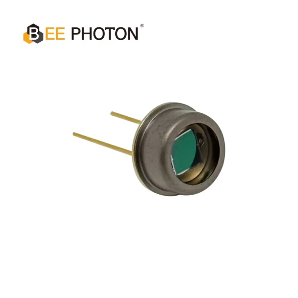
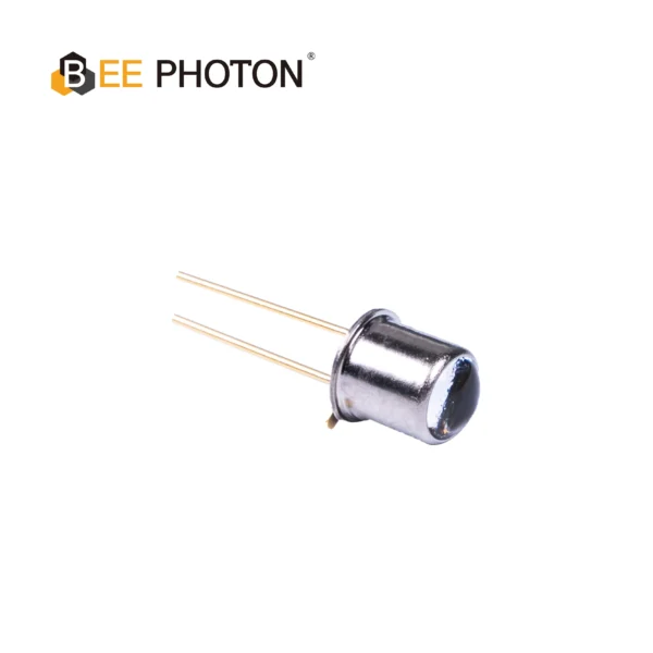
Si PIN Photodiode with low dark current (350-1060nm) PDCT14-001
Enhance your optical measurement equipment with our TO-packaged Si PIN photodiode. It features ultra-low dark current, high consistency, and a borosilicate window for durability. This high-performance Si PIN photodiode is optimized for demanding applications.
A Quick Story from the Trenches: Breaking the 0.1 NTU Barrier
Let me share a quick story about an OEM client we worked with (I’ll keep them anonymous). They were developing an inline water quality monitor for a municipal drinking water plant. The WHO recommends drinking water be kept below 1.0 NTU, and ideally < 0.1 NTU.
This client was stuck. No matter what they did, their sensor had a noise floor bouncing around 0.4 NTU. They couldn’t get it lower. They were using a generic off-the-shelf light sensor and blaming their software team for the noise.
They sent us their schematics. The issue was obvious. Their standard detector had a high junction capacitance and a dark current of around 5nA at room temp. We replaced their generic part with a custom BeePhoton Si PIN turbidity photodiode specifically binned for low dark current (< 50pA).
But we didn’t just stop there. We advised them to split the feedback loop of their TIA into a T-network to reduce the massive resistor values they were trying to use, and we added a 10pF feedback capacitor to cancel out the capacitance of the new turbidity photodiode.
The result? The noise floor plummeted to 0.02 NTU. They passed their certification tests the following month. It’s amazing what happens when you treat the turbidity photodiode as the critical heart of the instrument rather than a generic commodity.
Multi-Angle Turbidity: The Future or Just Marketing Fluff?
Nephelometry (90-degree scattering) is treated like a religion in this industry. But I’ll tell you right now, relying only on a single 90-degree turbidity photodiode in heavy wastewater with over 1000 NTU is a fool’s errand.
When water gets really dirty, a weird thing happens. The light from your LED hits the thick sludge, scatters multiple times, and actually gets absorbed before it can even reach the 90-degree turbidity photodiode. As the water gets dirtier, the signal at your turbidity photodiode actually drops. This is called multiple-scattering interference. A single 90-degree turbidity photodiode is effectively blind in that mud.
To fix this, high-end water quality sensors use multiple detectors.
- Transmitted light turbidity photodiode: Sits at 180 degrees (straight across). Measures how much light makes it through.
- Forward scatter turbidity photodiode: Sits around 10 to 30 degrees. Great for detecting larger particles.
- Backscatter turbidity photodiode: Sits at 135 to 145 degrees. When the water is basically mud, backscatter is the only reliable signal left.
By feeding the signals from a 90-degree turbidity photodiode, a backscatter turbidity photodiode, and a transmitted turbidity photodiode into a ratiometric algorithm, you can build an instrument that measures perfectly from 0.01 NTU all the way up to 10,000 NTU.
The math for a ratiometric setup usually looks like:
NTU = Signal_90 / (Signal_Transmitted + Signal_Forward + Signal_Back) * K
This cancels out errors from LED degradation and window fouling, because a dirty glass window reduces the light to every turbidity photodiode equally, keeping the ratio stable. It’s brilliant engineering, but it requires matching the spectral responses of every turbidity photodiode in the array perfectly. That’s something we handle natively at BeePhoton.
Si PIN Photodiode with low dark current (350-1060nm) PDCC07-003
Enhance your industrial automation systems with our low dark current Si PIN photodiode. This industrial automation photodiode (350-1060nm) offers superior precision and reliability.
FAQs on Turbidity Photodiode Integration
Q: What is the best wavelength to pair with a turbidity photodiode?
A: It depends on your compliance target. If you are aiming for ISO 7027, you must use an 860 nm infrared source. A standard Si PIN turbidity photodiode peaks around 850-900nm, making it highly sensitive to this exact wavelength. If you need EPA 180.1, you use a white tungsten lamp, and your turbidity photodiode must respond well across the visible spectrum (400-600nm).
Q: Why is my turbidity photodiode reading drifting wildly when the sensor gets warm?
A: You are experiencing dark current drift. A turbidity photodiode leaks a tiny amount of current even in the dark. This dark current doubles roughly every 10°C. If your sensor gets warm, the dark current spikes, your TIA amplifies it, and your software thinks the water just got dirtier. You need to upgrade to a low-dark-current turbidity photodiode and implement software temperature compensation.
Q: Can I use a standard PN junction instead of a Si PIN turbidity photodiode?
A: You can, but you shouldn’t if you care about low-end accuracy. Standard PN junctions have higher junction capacitance, which increases voltage noise gain in your amplifier circuit. A Si PIN turbidity photodiode has a much thicker depletion region, drastically lowering capacitance and improving response speed and signal-to-noise ratio for low NTU measurements.
Q: How does biological fouling on the sensor window affect my turbidity photodiode?
A: Algae or biofilm acts like a filter. It reduces the incident light entering the water, which means less scattered light reaches your turbidity photodiode. Your sensor will report an artificially low NTU. This is why many high-end units use mechanical wipers or ratiometric designs (using a reference turbidity photodiode) to calculate and cancel out window fouling.
Let’s Build Something Better
Look, building a reliable water quality sensor is hard enough without fighting your own components. You shouldn’t have to deal with endless noise filtering in software just because a cheap detector is drifting all over the place. We’ve helped dozens of OEMs hit that elusive 0.01 NTU noise floor by simply getting the front-end optics right.
Imagine pushing your next firmware update without having to write yet another complex temperature compensation patch, or never having to recall a batch of sensors because the baseline drifted in the field.
If you’re fed up with fighting optical noise and want to see what a properly binned, ultra-low dark current turbidity photodiode can do for your next hardware revision, let’s talk. You can reach out directly via contact us or drop a schematic question to our engineering team at info@photo-detector.com. We are always happy to help you select the exact Si PIN photodiodes that will make your next water quality monitor bulletproof.