Picking a position sensor for a galvanometer looks simple until the mechanical layout, control-loop bandwidth, and actual production cost land on the same spreadsheet.
Should you use an optical encoder? A magnetic encoder? Or photodetector based galvo feedback built around silicon PIN photodiodes?
There isn’t one answer for every scanner. An encoder may be the safer choice when absolute digital position and standardized communication matter most. Photodetector based galvo feedback usually becomes more attractive when low mass, compact packaging, fast analog response, and low-cost galvo positioning are the real priorities.
The catch is that datasheet resolution doesn’t tell the whole story. A 16-bit encoder can still perform poorly in a fast galvo loop if communication delay, mechanical inertia, or filtering adds too much phase lag. At the same time, a photodiode detector with no advertised “bit resolution” can produce extremely smooth position feedback when the optics, amplifier, and calibration are designed properly.
This guide compares photodetector based galvo feedback with digital optical and magnetic encoder systems from the viewpoint of system integrators, scanner manufacturers, and engineering decision-makers. We will look at dynamic response, accuracy, noise, weight, board space, calibration, reliability, and total cost—not just the sensor price.
What Is Photodetector Based Galvo Feedback?
Photodetector based galvo feedback uses one or more photosensitive areas to measure the position of a light spot, reflected beam, shutter edge, or moving optical pattern connected to the galvo shaft.
A typical system includes:
- An LED or infrared emitter
- An optical mask, reflector, vane, or moving light pattern
- A segmented silicon PIN photodiode
- One or more transimpedance amplifiers
- A differential or normalized position circuit
- An analog-to-digital converter, if the controller is digital
- Calibration data that maps detector output to mirror angle
In a two-segment design, the spot moves across two adjacent photodiode areas. When the spot is centered, both segments receive similar optical power. As it moves, one photocurrent rises while the other falls.
A simple differential signal is:
Position signal = I1 − I2
A normalized signal is:
Normalized position = (I1 − I2) / (I1 + I2)
Here, I1 and I2 are the photocurrents from the two detector segments.
Normalization matters because it reduces sensitivity to common changes in LED brightness, contamination, aging, and supply variation. It doesn’t remove every error, but it normally gives photodetector based galvo feedback a more stable position signal than a raw single-channel detector.
Unlike an encoder, this arrangement does not need to create and decode a large number of discrete optical or magnetic marks. The feedback can remain continuous and analog from the detector to the servo amplifier.
That difference is the heart of the analog optical feedback vs digital encoder debate.
How Optical and Magnetic Encoder Systems Work
An optical encoder normally reads a patterned disk, strip, or scale using an emitter and optical receiver. The pattern generates incremental pulses, sinusoidal signals, or an absolute digital code.
Incremental encoders usually provide:
- A and B quadrature channels
- An optional index channel
- Direction information
- Position obtained by counting pulses
Absolute encoders provide a unique position value after startup. Depending on the device, data may be transmitted through SPI, SSI, BiSS, or a proprietary interface.
A magnetic encoder replaces the optical scale with a magnet and magnetic sensing element, often based on Hall or magnetoresistive technology. It can be compact and resistant to dust, but magnetic field quality, magnet placement, nearby ferromagnetic material, and motor current can affect accuracy.
Major encoder suppliers provide a wide range of architectures. The Renishaw encoder systems overview, for example, shows how optical encoder products are divided by linear, rotary, incremental, and absolute measurement needs. US Digital encoder products also illustrate the mechanical and electrical variety behind the general term “encoder.”
The important point: saying “we will use an encoder” is not yet a sensor decision. The scale, readhead, interface, interpolation, bearing arrangement, shaft tolerance, and controller all affect the final result.
Photodetector Based Galvo Feedback vs Encoder Systems at a Glance
| Decision factor | Photodetector based galvo feedback | Optical encoder | Magnetic encoder |
|---|---|---|---|
| Output type | Continuous analog current or voltage | Digital pulses, serial data, or interpolated sine/cosine | Usually digital angle data or ABI/PWM |
| Dynamic response | Potentially very fast with a well-designed analog front end | Depends on readhead, interpolation, output rate, and interface latency | Depends heavily on internal sampling and digital filtering |
| Moving mass | Very low when the detector and emitter remain stationary | Disk, scale, hub, or coupling may add mass | Magnet adds limited mass but still needs alignment |
| Package size | Can be very compact | Often larger due to codewheel or scale geometry | Compact, although magnet spacing is critical |
| Position at power-up | Requires a known optical reference or calibration strategy | Incremental versions need homing; absolute versions do not | Absolute magnetic sensors can report startup angle |
| Resolution | Determined by signal-to-noise ratio, ADC, optics, and calibration | Defined by lines, interpolation, and counter architecture | Defined digitally, but effective accuracy is usually lower than nominal resolution |
| Linearity | Depends on spot shape, detector geometry, mechanics, and calibration | Depends on scale accuracy, eccentricity, interpolation, and mounting | Sensitive to magnet and shaft alignment |
| EMI sensitivity | Analog layout and shielding need care | Differential digital outputs can be robust | Magnetic field interference can be a concern |
| Cost structure | Detector, emitter, analog front end, and calibration | Readhead, scale or disk, hub, interface, assembly | IC, magnet, PCB, alignment, and calibration |
| Best fit | High-dynamic, low-mass, compact galvo servo loops | Standardized metrology or absolute digital position | Compact general-purpose rotary sensing |
This table is a starting point, not a winner announcement. Galvo sensor selection should be based on the closed-loop scanner rather than one headline parameter.
Si PIN photodiodes for Galvo PDC-C2929
The PDC-C2929 is a budget-friendly 920nm silicon PIN photodiode chip. This 920nm silicon PIN photodiode offers stable, cost-effective scanner position tracking.
Dynamic Response: Where Photodetector Feedback Often Wins
A galvanometer is not a slow positioning stage. In beam steering, laser marking, imaging, LiDAR, optical coherence systems, and tracking applications, the mirror may reverse direction thousands of times per second.
Extra delay is expensive in a high-bandwidth loop.
Photodetector based galvo feedback can generate photocurrent almost immediately after the optical spot moves. The practical response is then limited by:
- Photodiode junction capacitance
- Photodiode responsivity at the emitter wavelength
- Transimpedance amplifier bandwidth
- Feedback resistor and capacitor values
- PCB parasitic capacitance
- ADC sampling and digital processing, if used
- Mechanical and optical geometry
A useful first-order relationship between rise time and bandwidth is:
Bandwidth ≈ 0.35 / rise time
So, a front end with a 10 microsecond rise time has an approximate bandwidth of 35 kHz. That doesn’t mean the galvo control bandwidth should automatically be 35 kHz. Mechanical resonance, phase margin, amplifier delay, and mirror inertia still set practical limits.
Encoder systems introduce different delays. An incremental optical encoder may generate edges quickly, but position estimation at low speed can become coarse if the controller relies only on pulse counting. A serial absolute encoder may deliver fine digital resolution, yet its sampling, internal filtering, transmission, and controller processing create latency.
Delay produces phase lag:
Phase lag in degrees = −360 × frequency × delay
At 5 kHz, a 20 microsecond delay adds 36 degrees of phase lag. That’s not a tiny detail. It can be the difference between a stable servo and one that rings, overshoots, or needs a lower control bandwidth.
This is why photodetector based galvo feedback often feels better in fast analog loops even when an encoder claims more bits.
Don’t Confuse Resolution with Servo Performance
A digital encoder with N bits divides its measurement range into:
Number of positions = 2^N
For a full 360-degree range:
Angular step = 360 degrees / 2^N
A 16-bit encoder therefore has a nominal digital step of about 0.00549 degrees.
Sounds excellent. But a galvo may use only a small angular range, and nominal resolution is not the same as accuracy, repeatability, noise, or update speed. The lower bits may move because of magnetic noise, optical interpolation error, shaft vibration, or internal signal processing.
Photodetector based galvo feedback has no fixed physical “step” before digitization. Its effective resolution depends on the slope of the position signal and the total noise.
A practical estimate is:
Position noise = output voltage noise / position sensitivity
If the detector circuit changes by 0.8 volts per degree and the measured RMS noise is 0.4 millivolts, the corresponding RMS angular noise is:
0.0004 volts / 0.8 volts per degree = 0.0005 degrees
That calculation is much more useful than comparing an encoder’s bit count with an ADC bit count.
Analog Optical Feedback vs Digital Encoder: Signal Quality
The strongest argument for photodetector based galvo feedback is smooth, low-latency position information. The strongest argument against it is that analog quality depends on the complete circuit and optical design.
Photodiode Noise Sources
A PIN photodiode produces shot noise. Its current noise can be estimated as:
Shot noise current = square root of (2 × q × I × B)
Where:
- q is the electron charge, approximately 1.602 × 10^−19 coulomb
- I is the average photodiode current in amperes
- B is the measurement bandwidth in hertz
The amplifier also adds voltage noise, current noise, resistor thermal noise, and power-supply noise. Higher bandwidth passes more noise, so “make it as fast as possible” is not good design advice.
Photodiode capacitance deserves attention too. Larger active areas make optical alignment easier, but they generally bring more capacitance. More capacitance can reduce transimpedance bandwidth or make the amplifier unstable unless the feedback network is adjusted.
The Analog Devices Photodiode Circuit Design Wizard is a useful reference for exploring how detector capacitance, photocurrent, amplifier selection, gain, noise, and bandwidth interact.
Encoder Error Sources
Encoder systems have their own less-obvious problems:
- Codewheel eccentricity
- Scale graduation error
- Readhead alignment
- Interpolation error
- Magnet tilt or displacement
- Harmonic error from an imperfect magnetic field
- Quantization
- Missed incremental counts
- Serial update latency
- Internal filtering
- Shaft or hub runout
A magnetic device may advertise 14-bit output while delivering considerably less absolute angular accuracy. That’s not dishonest; resolution and accuracy describe different things. Still, buyers regularly compare the bit number and miss the actual error plot.
For galvo sensor selection, ask for maximum integral nonlinearity, repeatability, noise, update rate, latency, and temperature drift. If the vendor provides only resolution, the selection isn’t done.
Size, Weight, and Mechanical Inertia
Weight matters more in a galvo than in a slow motor encoder.
A traditional encoder may require a code disk or magnet mounted on the moving shaft. It may also need a hub, adhesive, retainer, bracket, readhead clearance, and a protective cover. Even a small added component can change rotor inertia or shift a mechanical resonance.
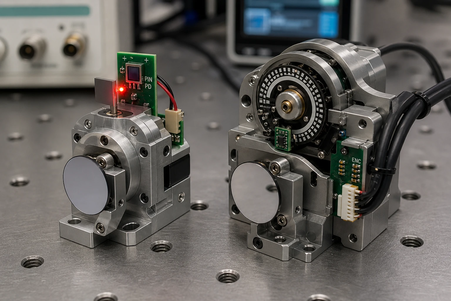
Photodetector based galvo feedback can keep the PIN photodiode and emitter on a stationary PCB. Only a lightweight vane, reflector, or optical feature needs to move with the rotor.
This gives photodetector based galvo feedback several packaging advantages:
- Less added shaft mass
- No heavy codewheel
- Smaller axial stack
- Fewer precision rotating parts
- More freedom to place electronics around the galvo body
- Easier integration into narrow optical assemblies
The exact benefit depends on the optical mechanism. A badly designed shutter can still add inertia, and a long vane can introduce vibration. Keep the moving optical element stiff, balanced, and close to the rotational axis where possible.
In compact scanners, photodetector based galvo feedback may also reduce cable count because the detector can sit directly beside the servo electronics. Short analog traces help with noise and capacitance. It’s a nice double win, when the layout allows it.
Si PIN photodiodes for Galvo PDC-2C3432-NIR-B
The PDC-2C3432-NIR-B is a specialized segmented PIN photodiode chip engineered for precise differential position feedback in high-speed galvanometer scanners. Integrating this dual-channel segmented PIN photodiode chip allows systems to obtain accurate angular tracking with minimal signal noise.
Cost Comparison: Sensor Price Is Only the First Line
Low-cost galvo positioning does not mean buying the cheapest detector. Total cost includes components, assembly, calibration, testing, rejects, mechanical tolerance, firmware, and service risk.
| Cost area | Photodetector based galvo feedback | Encoder system |
|---|---|---|
| Sensor component | PIN detector can be economical at volume | Varies widely by encoder type and accuracy |
| Optical source | LED and drive circuit required | Optical encoders include or require an emitter; magnetic encoders do not |
| Analog electronics | Transimpedance and conditioning circuit required | Incremental receivers or serial interface may be required |
| Mechanical parts | Reflector, vane, or optical mask | Codewheel, scale, magnet, hub, bracket, or coupling |
| Processor workload | ADC reading and calibration | Counting, serial communication, interpolation, or position decoding |
| Calibration | Usually required for accurate angle mapping | Often required for mounting and eccentricity errors |
| Assembly tolerance | Optical spacing and spot alignment matter | Readhead gap, codewheel centering, or magnet alignment matters |
| Production test | Signal balance, range, noise, and linearity | Counts, index, communication, runout, or magnetic error |
| Field replacement | May require matched calibration | Standard encoder modules may be easier to replace |
For a fair quotation, compare complete BOMs at the same accuracy and bandwidth. Do not compare a bare photodiode chip with a fully packaged absolute encoder and call the difference “savings.” That’s spreadsheet theater.
Photodetector based galvo feedback tends to reach its best cost position when:
- Annual volume justifies a dedicated PCB and fixture
- The galvo uses a limited angular range
- The control loop already processes analog signals
- Low moving mass has real performance value
- The mechanical design can include a simple optical target
- Factory calibration is already part of production
- Absolute 360-degree position is unnecessary
An encoder can be cheaper overall for low-volume builds because development time has a cost too. A standard module with a documented interface may get a prototype running faster than a custom optical feedback assembly.
That opinion isn’t always popular with component vendors, but it is true.
Choosing the Right Si PIN Photodiode for a Galvo
The detector should be selected together with the emitter, optical geometry, amplifier, and required angle range.
Key parameters include:
Spectral Responsivity
Match the PIN photodiode to the emitter wavelength. Silicon photodiodes respond across visible and near-infrared wavelengths, but responsivity changes with wavelength.
The US National Institute of Standards and Technology maintains information on photodetector calibration services, while Hamamatsu’s photodiode resources provide useful background on silicon photodiode characteristics.
For near-infrared galvo feedback, BeePhoton offers options including the PDC-C2928-NIR-B 940 nm PIN photodiode chip and the PDC-C2929 920 nm silicon PIN photodiode.
The product name or target wavelength alone isn’t enough. Confirm responsivity, dark current, capacitance, active-area dimensions, package or die format, operating temperature, and available test data before locking the design.
Active Area and Segmentation
A larger active area can improve optical tolerance, but may increase capacitance. A smaller area may support higher bandwidth while demanding tighter alignment.
Segmented detectors are particularly useful for differential photodetector based galvo feedback. BeePhoton’s PDC-2C3432-NIR-B segmented PIN photodiode chip is intended for designs that need multiple photosensitive regions on one chip.
For a two-segment detector, check:
- Segment dimensions
- Gap width
- Segment matching
- Capacitance per segment
- Dark current per segment
- Optical crosstalk
- Die placement tolerance
- Wire-bond pad arrangement
The gap between segments affects the transfer curve. Too wide, and a dead zone may appear. Too narrow, and optical scattering or manufacturing tolerances can complicate channel separation.
Detector Capacitance
Detector capacitance and amplifier input capacitance directly affect transimpedance stability.
A simplified transimpedance gain is:
Output voltage = photodiode current × feedback resistance
If photocurrent is 50 microamps and the feedback resistor is 20 kilohms:
Output voltage = 50 microamps × 20 kilohms = 1 volt
Raising the resistor increases sensitivity, but usually reduces bandwidth and may increase output saturation risk. There is no magic resistor value. Model the expected photocurrent range, amplifier gain bandwidth, capacitance, and feedback capacitor together.
Dark Current and Temperature
Dark current adds offset and shot noise. In a strong illuminated feedback system, it may be small compared with photocurrent. At low light levels or high temperatures, it becomes more relevant.
Measure the complete photodetector based galvo feedback assembly at minimum and maximum operating temperatures. LED output, detector responsivity, amplifier offset, adhesive movement, and mechanical dimensions can all drift at once.
A Practical Galvo Sensor Selection Process
A clean decision process prevents weeks of arguing over datasheets.
1. Define the Mirror-Side Requirement
Write down:
- Mechanical scan angle
- Optical scan angle
- Target settling time
- Maximum tracking error
- Repeatability requirement
- Control-loop frequency
- Operating temperature
- Shock and vibration limits
- Allowed moving mass
- Available PCB area
- Target production cost
Be clear about mechanical versus optical angle. For a flat mirror, the reflected beam usually moves by twice the mechanical mirror angle.
2. Build an Error Budget
For photodetector based galvo feedback, include:
- Detector noise
- Amplifier noise and offset
- ADC noise
- LED drift
- Optical nonlinearity
- Detector segment mismatch
- Mechanical play
- Calibration residual
- Temperature drift
For the encoder option, include:
- Quantization
- Scale or magnetic accuracy
- Eccentricity
- Interpolation error
- Mounting tolerance
- Communication delay
- Missed-edge risk
- Temperature drift
Use root-sum-square only for errors that are independent and random:
Total RMS error = square root of (error1² + error2² + error3² + …)
Worst-case systematic errors should generally be added directly or removed through calibration. Mixing every number into a root-sum-square calculation can make a weak design look weirdly good.
3. Measure Latency, Not Just Update Rate
An encoder may output data at 20 kHz but still include internal delay. A photodetector circuit may have adequate small-signal bandwidth but saturate during a large step.
Test both with:
- Small sine-wave motion
- Large angle steps
- Direction reversals
- Slow ramps
- Temperature variation
- Supply variation
- Real motor current flowing
Compare command, physical position, and reported feedback on the same time base. This quickly exposes filtering and phase delay.
4. Calibrate the Real Assembly
Photodetector based galvo feedback is often nonlinear across a wide angle because the spot shape, path, detector geometry, and reflector angle all change.
A practical calibration can use:
- A linear gain and offset for a narrow range
- A piecewise-linear table
- A polynomial correction
- A stored lookup table with interpolation
Avoid high-order polynomial fitting unless the residual error genuinely improves across temperature and production units. High-order curves can behave badly between calibration points.
5. Compare Total Production Cost
Ask each team to provide:
- Component cost at the same annual volume
- PCB area
- Assembly time
- Calibration time
- Fixture cost
- Expected yield loss
- Required firmware work
- End-of-line test time
- Supply-chain alternatives
- Field service implications
Photodetector based galvo feedback often wins in a mature, volume-controlled product. A standard encoder often wins in an early prototype or low-volume industrial machine. Context decides.
Recommended Bench Tests Before Design Freeze
A datasheet cannot reproduce your reflector, LED angle, amplifier layout, motor field, or galvo mechanics.
Run these tests on at least several assemblies:
| Test | What to record | Why it matters |
|---|---|---|
| Static angle sweep | Output, linearity residual, hysteresis | Shows usable range and calibration need |
| Repeated center return | Mean and standard deviation | Reveals repeatability and mechanical play |
| Frequency sweep | Gain and phase | Shows usable loop bandwidth |
| Large step | Settling, saturation, recovery | Exposes large-signal limitations |
| Temperature sweep | Offset, gain, linearity | Finds drift that room testing misses |
| LED current variation | Position change after normalization | Checks rejection of optical-power drift |
| Motor current test | Feedback noise with drive active | Finds coupling and grounding problems |
| Supply disturbance | Output shift and recovery | Checks power-supply rejection |
| Mechanical vibration | Position output and resonance | Reveals loose or flexible optical parts |
For photodetector based galvo feedback, save the two raw detector channels as well as the final differential output. If only the processed position signal is logged, LED degradation or one weak segment may remain hidden.
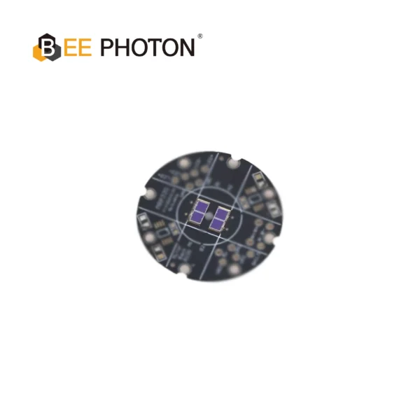
Si PIN photodiodes for Galvo PDC-C2928-NIR-B
Optimize scanning with our 940nm PIN photodiode chip, PDC-C2928-NIR-B. This 940nm PIN photodiode chip ensures precise galvo position sensing and low noise.
Common Design Mistakes
Using Only I1 − I2
The raw difference is easy, but it changes when total light changes. Whenever the signal range permits, compare it with the normalized result:
(I1 − I2) / (I1 + I2)
Add denominator limits so the circuit or software does not divide by a near-zero value during startup, blockage, or emitter failure.
Putting Too Much Gain in One Stage
High transimpedance gain can cause saturation and poor recovery. Splitting gain between the transimpedance stage and a later voltage amplifier may give a better bandwidth and dynamic-range tradeoff.
Routing Motor Current Beside Detector Traces
Photodiode currents can be small. Keep detector nodes short, control the return path, separate them from PWM switching loops, and place decoupling close to the amplifier.
Photodetector based galvo feedback isn’t automatically noisy. Careless PCB layout is noisy.
Calibrating One Golden Sample
Calibration based on one hand-built unit hides production spread. Characterize multiple emitters, detector lots, PCBs, and mechanical assemblies. The goal is not to make one scanner beautiful; it is to make production predictable.
Selecting by Price Before Geometry
A cheaper photodiode that forces tighter alignment, a larger PCB, or a slower amplifier can raise total cost. Galvo sensor selection should start with optical geometry and system requirements, then move to price.
Which System Should You Choose?
Choose photodetector based galvo feedback when you need:
- Very low feedback latency
- Smooth analog position information
- Low rotor mass
- Compact packaging
- A limited galvo angle range
- A custom high-volume design
- Direct integration with an analog servo loop
- Flexible optical and mechanical geometry
Choose an optical encoder when you need:
- A standard metrology architecture
- High absolute accuracy from a qualified scale
- Long measurement travel or full rotation
- Digital noise immunity over longer cabling
- Traceable encoder specifications
- Easier module replacement
Choose a magnetic encoder when you need:
- Compact absolute angle sensing
- Resistance to dust or optical contamination
- Moderate accuracy at a practical cost
- Simple PCB integration
- No LED or optical path
For many fast beam-steering products, photodetector based galvo feedback gives the best combination of dynamics, size, and manufacturing cost. For laboratory instruments or low-volume systems where development time dominates, an off-the-shelf encoder can still be the smarter purchase.
No sensor architecture rescues a poor mechanical design. The galvo rotor, bearings, mirror, amplifier, detector, and controller need to be treated as one system.
Get a Photodiode Recommendation for Your Galvo Design
A galvo feedback problem usually becomes easier once real numbers replace the vague stuff: emitter wavelength, expected spot size, detector distance, angle range, target bandwidth, and available PCB space.
BeePhoton supplies silicon PIN photodiode options for near-infrared and segmented sensing designs. You can browse the BeePhoton photodetector website to review the available detector categories and possible starting points.
If your current encoder is too large, too heavy, too slow, or simply too expensive at production volume, photodetector based galvo feedback is worth testing rather than dismissing as “just analog.”
Send your wavelength, drawing, estimated photocurrent, active-area requirement, annual quantity, and target response time through the BeePhoton contact page. You can also contact the team at info@photo-detector.com to request product details, samples, or a quotation.
A short technical review before PCB release can prevent the classic headache: discovering that the detector fits the schematic but not the optical spot.
Frequently Asked Questions
Is photodetector based galvo feedback more accurate than an encoder?
Not automatically. Photodetector based galvo feedback can provide excellent repeatability and very low latency, but absolute accuracy depends on detector geometry, optical alignment, signal conditioning, mechanics, and calibration.
A high-grade optical encoder may offer better documented absolute accuracy. A photodiode system may still produce better closed-loop dynamic performance because its feedback is smoother and faster. Compare measured angle error and phase delay, not just nominal resolution.
Can photodetector based galvo feedback provide absolute position?
Yes, within a defined optical range, provided each detector output corresponds to a unique position. A segmented detector and shaped optical target can generate an absolute analog position signal without counting pulses.
The controller still needs a fault strategy for blocked light, low LED output, saturation, or a signal outside the calibrated range.
Is an analog photodiode signal too noisy for precision galvo control?
Not when the optical power, transimpedance amplifier, grounding, shielding, and bandwidth are designed properly. Noise becomes a problem when designers use excessive bandwidth, long high-impedance traces, weak illumination, or poor motor-current routing.
Measure RMS output noise and divide it by volts-per-degree sensitivity. That gives a realistic angular noise figure.
Does a magnetic encoder work near a galvo motor?
It can, but test it in the real magnetic environment. Motor current, nearby steel, magnet tilt, radial displacement, and axial gap can introduce angle error. Do not evaluate the encoder only on a quiet bench away from the motor.
Which photodiode structure is best for low-cost galvo positioning?
A two-segment PIN photodiode is often a practical choice because it supports differential and normalized position measurement. A single detector may work with a moving shutter, while more segments can support wider ranges, fault detection, or more complex position calculations.
The best structure depends on spot size, travel direction, alignment tolerance, bandwidth, and available amplifier channels.
How should I compare analog optical feedback vs digital encoder latency?
Apply known motion and record the physical reference, sensor output, and controller reading on the same oscilloscope or synchronized acquisition system. Measure phase across frequency, not only the delay from one large step.
Include ADC conversion, serial transmission, digital filters, and firmware scheduling. Those “small” delays pile up fast in a high-dynamic galvo loop.
Can photodetector based galvo feedback reduce production cost?
Yes, especially in compact, higher-volume products where a stationary detector and simple moving optical target replace a codewheel, hub, readhead, and related assembly work.
Savings are not guaranteed. Include calibration time, fixtures, yield, amplifier components, LED cost, and optical alignment in the calculation. The lowest component price isn’t always the lowest finished-system cost.
What information is needed to request a galvo photodiode quotation?
Prepare the emitter wavelength, detector arrangement, target active area, expected photocurrent, required bandwidth, operating temperature, die or package preference, annual quantity, and any mechanical drawings.
For a tailored photodetector based galvo feedback recommendation, use the BeePhoton contact form or email info@photo-detector.com.