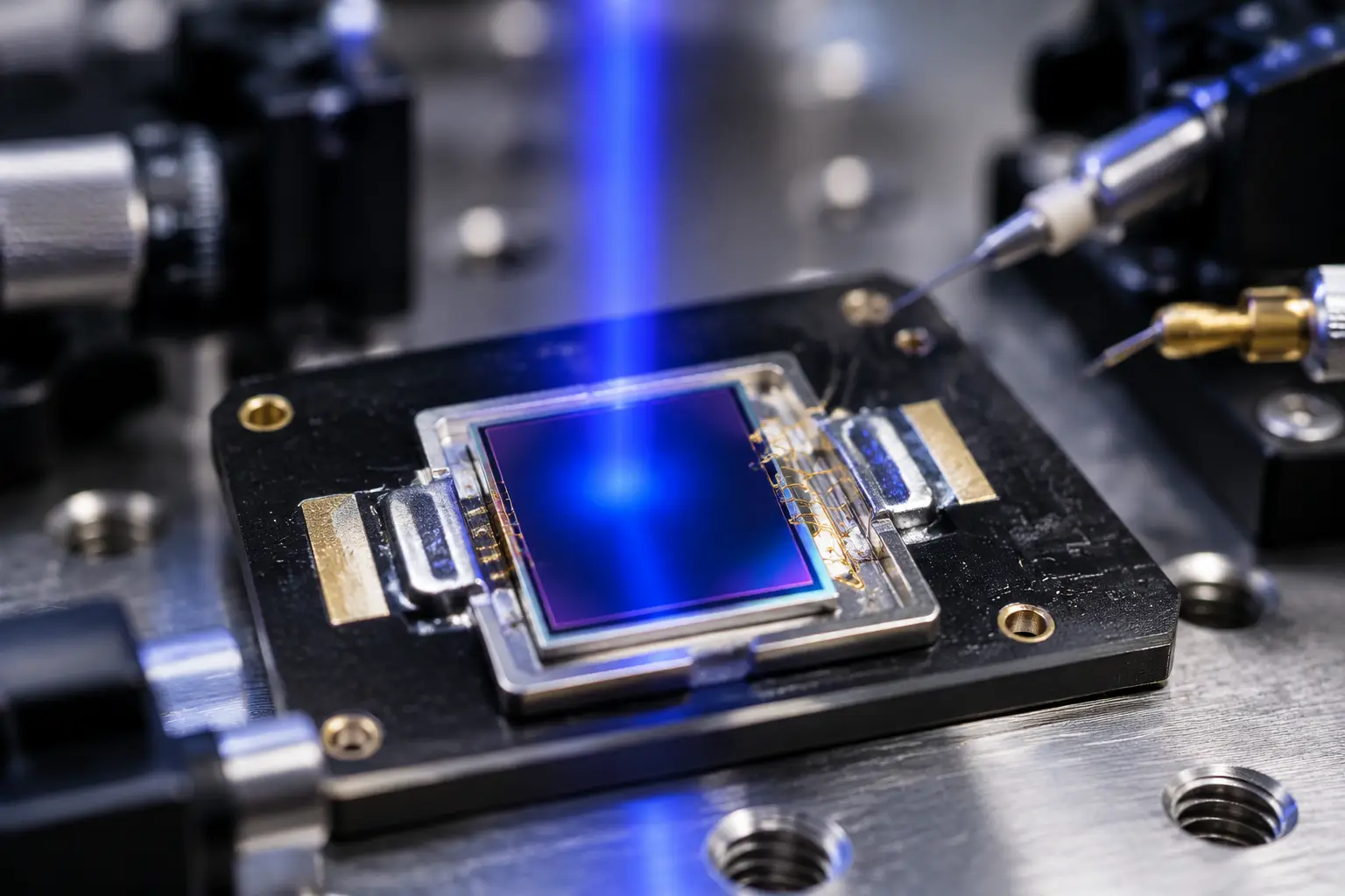
If you have ever been called out to an industrial client site in mid-July because an outdoor security gate refuses to close, or spent a freezing January morning debugging perimeter infrared beams generating phantom alarms at dawn, you know the harsh reality of outdoor optoelectronics. Components that behave impeccably on an air-conditioned test bench often fall apart when exposed to real-world weather.
When an optical sensor is bolted inside an aluminum housing under the desert sun, ambient temperatures easily exceed 40°C, and internal enclosure temperatures can soar past 80°C. Six months later, that same enclosure might freeze at -30°C in blowing snow. Most design teams instinctively try to fix temperature problems in firmware. They write adaptive baseline trackers, expand digital comparator windows, or add endless calibration passes.
Band-aids in code cannot fix physics. When your sensing junction swings across a 120°C temperature span, standard optical diodes suffer from massive thermal drift. To build rock-solid outdoor equipment, you must resolve the drift at the hardware level. Designing your analog front end around a high-quality low temperature drift photodetector eliminates false triggers, stops amplifier clipping, and keeps automated barriers running reliably year-round.
Signal Path Breakdown: Where Thermal Drift Destroys Your Signal
Understanding why outdoor automated systems fail starts with looking at the complete signal path. In perimeter security barriers, highway toll sensors, and exposed logistics conveyors, the optical signal has to survive multiple environmental roadblocks:
Signal Chain at a Glance:
- Modulated NIR Emitter (850nm / 940nm): Fires high-frequency optical pulses across the detection zone.
- Outdoor Protective Window: Suffers from ambient sunlight, dust accumulation, frost, and condensation.
- Daylight-Filter Optical Resin: Strips out visible solar wavelengths while allowing near-infrared signals to pass through.
- Low Temperature Drift Photodetector: Converts incoming photons into electrical current without thermal dark current runaway at +85°C or responsivity loss at -40°C.
- Transimpedance Amplifier (TIA): Converts tiny photocurrents into usable voltages without clipping against supply rails.
- Bandpass Filtering & Comparator: Isolates pulse signals from ambient DC offsets to detect valid target breaks.
If your photodiode drifts excessively across temperature, steps 4 and 5 fail instantly. When the photodiode leaks current during a heatwave, the amplifier output baseline creeps upward until the signal rails out, creating permanent blindness or phantom beam-break triggers.
The Cold, Hard Physics: What Happens Inside the Junction?
Outdoor optical automation systems—especially active infrared perimeter barriers, pedestrian turnstiles, and sorting conveyors—rely on detecting small changes in light transmission. When temperature swings wildly, silicon photodiodes suffer from two major physical issues: dark current explosion and spectral responsivity shift.
“Treating photodiode thermal drift as a software calibration problem is an expensive engineering mistake. A saturated transimpedance amplifier cannot deliver data, no matter how sophisticated your firmware filtering is.”
1. High-Temperature Dark Current Avalanche
Dark current (Id) is the leakage current flowing through a reverse-biased photodiode when no light enters the junction. In an ideal sensor, this current would stay near zero. In real-world silicon PIN junctions, thermally generated electron-hole pairs double roughly every 8°C to 10°C.
You can calculate this behavior using the classic relationship derived from the Shockley diode equation:
Id(T) = Id0 * 2^((T – T0) / 10)
Where:
- Id(T) represents dark current at operating temperature T
- Id0 represents baseline dark current at room temperature T0 (typically 25°C)
- T is junction temperature in degrees Celsius
Consider an automated parking gate controller installed in direct sunlight. While the outdoor air might measure 42°C, solar radiation heating the dark powder-coated enclosure can easily drive internal PCB temperatures to 85°C—a ΔT of 60°C above room temperature.
If you choose a generic commercial PIN photodiode with an initial Id0 of 4 nA at 25°C:
Id(85°C) ≈ 4 nA * 2^((85 – 25) / 10) = 4 nA * 2^6 = 256 nA
When your transimpedance amplifier circuit utilizes a 2 MΩ feedback resistor (Rf) to detect weak beams across an open span, that thermal leakage current produces an unintended DC baseline voltage shift:
Vout_drift = Id * Rf = 256 nA * 2 MΩ = 512 mV
In a modern 3.3V single-supply analog system, losing over half a volt to baseline drift eats up your operating headroom. Add in ambient solar light, and your operational amplifier easily saturates against the supply rail. When the emitter LED fires, the clipped receiver cannot register the pulse, and the controller triggers a false alarm.
Using an industrial low temperature drift photodetector solves this failure mode at the silicon level. With room-temperature baseline dark current specified below 0.5 nA, high-temperature leakage at 85°C remains below 32 nA. This preserves critical dynamic range across your analog front end.
2. Winter Bandgap Shift and Responsivity Collapse
The opposite failure strikes in winter. Outdoor security barriers and industrial gate sensors rely heavily on 850 nm and 940 nm near-infrared (NIR) wavelengths to cut through morning fog and operate invisibly.
Silicon features an indirect bandgap. As temperatures drop toward -40°C, the silicon crystal lattice contracts, increasing the energy gap (Eg) needed to transition electrons from the valence band to the conduction band. This bandgap shift follows the well-established Varshni empirical formula:
Eg(T) = Eg(0) – (alpha * T^2) / (T + beta)
For silicon substrates:
- Eg(0) = 1.166 eV
- alpha = 4.73e-4 eV/K
- beta = 636 K
As Eg widens in sub-zero environments, silicon becomes increasingly transparent to longer NIR wavelengths. Absorption depth extends deeper into the substrate, lowering responsivity at 940 nm.
A standard silicon sensor with a room-temperature responsivity of 0.60 A/W can see its sensitivity drop below 0.40 A/W at -40°C. If your emitter LED is also experiencing power degradation due to cold supply lines, your overall signal strength plunges. The comparator drops below its threshold, interpreting the weak signal as a broken beam.
A well-designed low temperature drift photodetector balances depletion region depth and substrate resistivity. This optimization limits the temperature coefficient of responsivity (TCR) to minimal values across -40°C to +100°C, ensuring consistent pulse amplitudes through freezing winter weather.

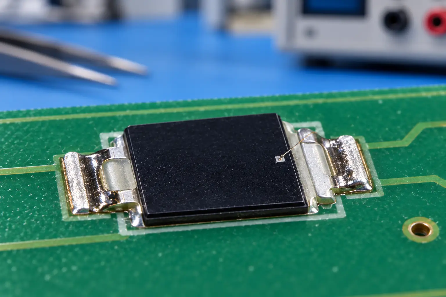
Si PIN photodiode PDCP08 Series PDCP08-511
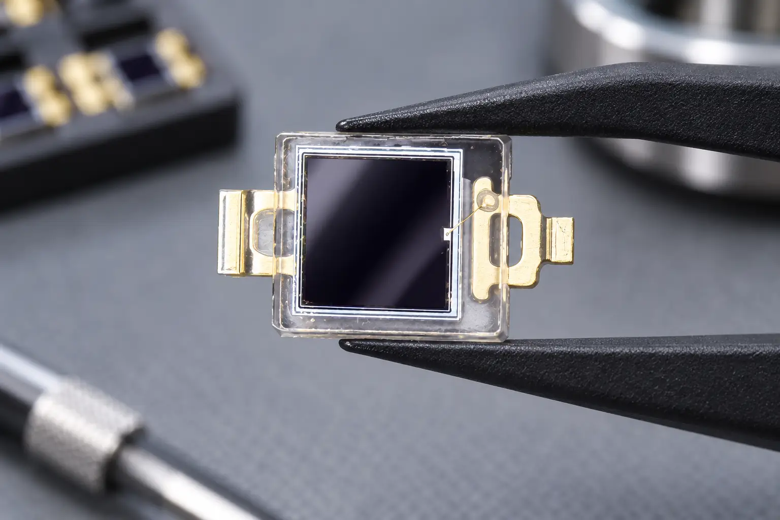
The PDCP08-511 is a high-performance Black Epoxy PIN Photodiode designed for precision infrared applications. Encased in a special black epoxy resin, this sensor effectively acts as a daylight filter, blocking visible light interference while maximizing sensitivity at 940nm. With a large 2.9×2.9mm active area and low dark current, it ensures reliable signal detection for optical switches and remote control systems, even in noisy ambient light environments.
Component Selection Matrix: Standard vs. Low-Drift Photodiodes
Selecting components out of generic catalogs often leads to unpredictable field failures. The table below illustrates the critical differences between standard consumer-grade diodes and an industrial-grade low temperature drift photodetector engineered by BeePhoton.
| Engineering Metric | Standard Commercial Photodiode | Industrial Low Temperature Drift Photodetector | Real-World Automation Impact |
|---|---|---|---|
| Operating Temperature | -20°C to +70°C | -40°C to +100°C | Eliminates thermal shutdown inside sealed enclosures |
| Dark Current @ 25°C (Vr=10V) | 2.0 nA to 15.0 nA | 0.1 nA to 0.8 nA | Preserves dynamic range in high-gain TIA stages |
| Dark Current @ 85°C | 150 nA to 800 nA | 12 nA to 40 nA | Prevents midday summer amplifier saturation |
| Responsivity Drift (940nm) | > 0.35% / °C | < 0.11% / °C | Prevents false alarms during sub-zero freezes |
| Optical Encapsulation | Clear casting epoxy | Daylight-filtering black epoxy resin | Rejects sunlight while transmitting NIR beams |
| UV Degradation (1,000 hrs) | Yellowing, clouding (>20% loss) | UV-stabilized resin (<2% shift) | Maintains transmission over multi-year deployments |
| Breakdown Voltage (Vbr) | 20 V to 30 V | > 50 V | Provides robust protection against industrial transients |
For compact automated equipment where board space is tight, the PDCP08-502 surface-mount PIN photodiode combines an ultra-compact 2.9×2.8mm footprint with low thermal leakage across the -40°C to +100°C range.
If your outdoor application requires microsecond pulse tracking for high-frequency safety barriers, the PDCP08-501 high-speed photodiode delivers low junction capacitance and fast rise times without sacrificing thermal stability.
Optical Packaging: Why Clear Epoxy Fails in Outdoor Environments
Silicon performance is only one piece of the puzzle. The resin packaging protecting the silicon chip plays an equally important role in field reliability.
Standard commercial photodiodes typically use clear casting resin. While effective in clean, indoor environments, clear packaging creates severe problems when placed outdoors:
- Sunlight-Induced DC Saturation: Direct sunlight delivers up to 1,000 W/m² of broadband energy. Clear resin allows visible wavelengths to flood the silicon, generating hundreds of microamps of continuous DC photocurrent that immediately saturates the analog receiver.
- Thermal Expansion Mismatch: Low-grade epoxies exhibit high coefficients of thermal expansion (CTE). Repeated cycling between freezing nights and scorching afternoons causes mechanical fatigue and bond-wire shearing.
- UV Clouding and Discoloration: Exposure to solar UV rays turns cheap clear epoxy yellow and brittle over time, steadily degrading optical transmission.
“A clear epoxy photodiode mounted outside acts like an unregulated solar cell swamping your amplifier. For unshaded outdoor equipment, daylight-filtering resin is mandatory.”
| Optical Band | Wavelength Spectrum | Clear Casting Resin | Daylight-Filter Black Epoxy | Operational Advantage |
|---|---|---|---|---|
| UV & Visible Light | 300 nm to 700 nm | 85% to 92% Transmission | Under 2% Transmission | Blocks solar wash, spotlights, and car headlights |
| Near-Infrared (NIR) | 850 nm to 1050 nm | 88% to 94% Transmission | Over 85% Transmission | Preserves maximum pulse amplitude for 850nm/940nm beams |
Using a specialized low temperature drift photodetector like the PDCP08-511 daylight-filter PIN diode eliminates solar saturation. Its cast black resin blocks visible light below 700 nm while allowing near-infrared signals to pass with minimal attenuation.
By filtering out visible light before it reaches the silicon die, this setup eliminates over 90% of solar DC offset. For long-term installation reliability, verify that your packaging materials comply with ASTM G154 accelerated weathering standards.
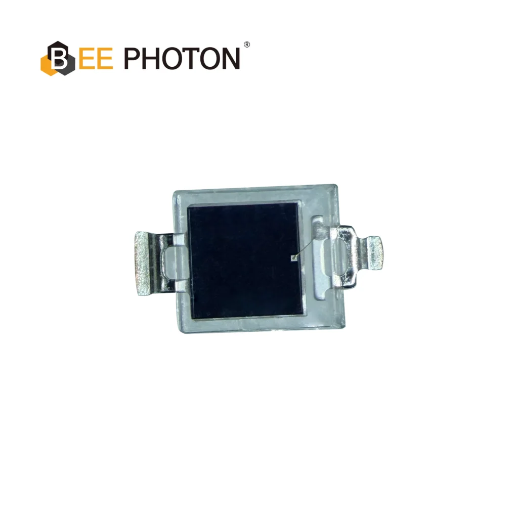
Si PIN photodiode PDCP08 Series PDCP08-501
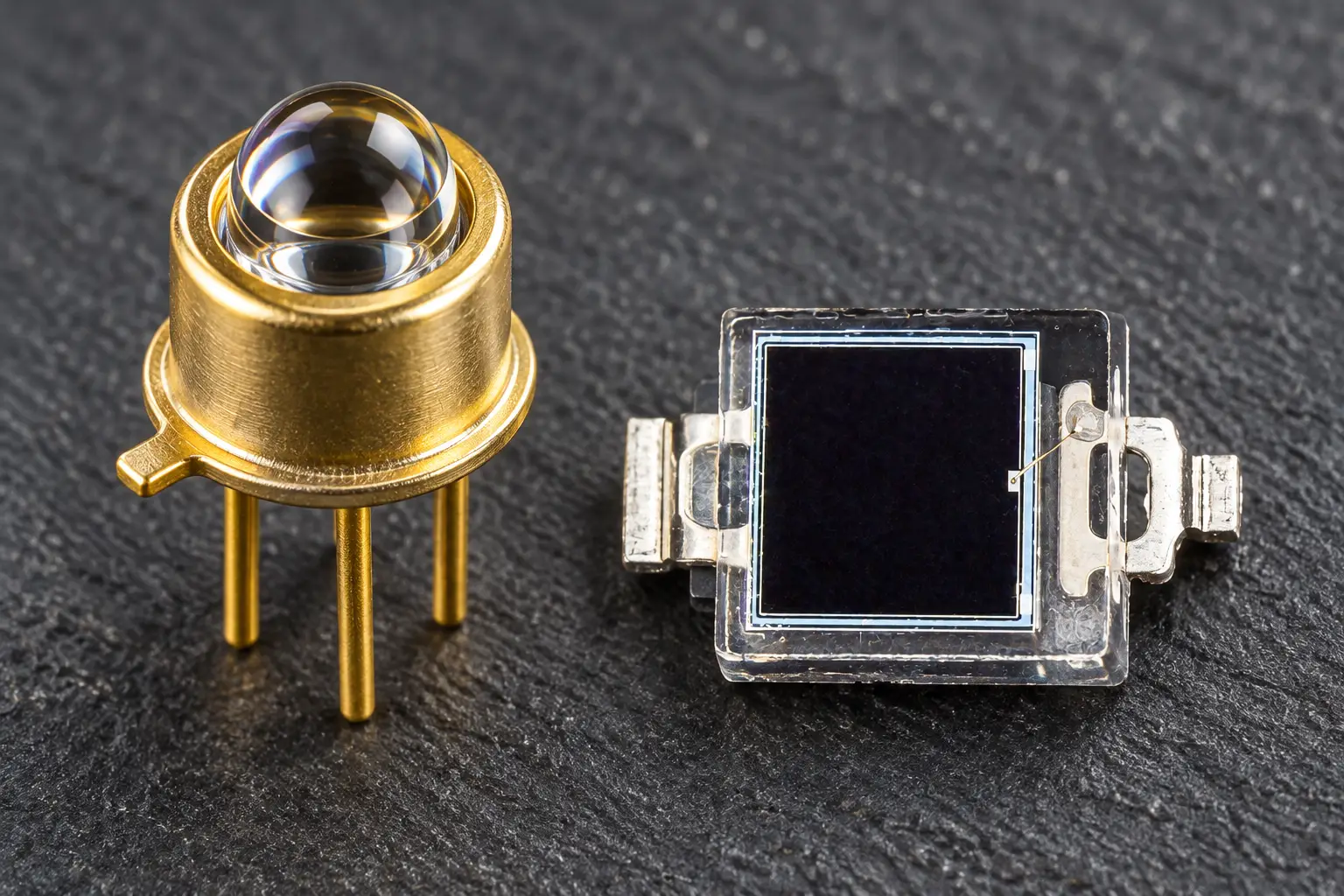
High-Performance Detection: The PDCP08-501 is a high-speed Silicon PIN Photodiode with a transparent window.
Key Specs: Featuring a 2.9×2.9mm active area, this PIN photodiode offers low dark current and high responsivity, making it an ideal sensor for general optical switches and light detection systems.
Analog Circuit Architectures for Maximum Thermal Immunity
Even with an industrial low temperature drift photodetector, your PCB layout and schematic must reinforce thermal resilience. Connecting a photodiode directly to a basic DC comparator will lead to false trips whenever weather conditions shift.
Circuit Topology: Thermal-Immune AC-Coupled Photodiode Receiver
Stage 1: Photodiode Bias & Transimpedance Stage
- Bias Configuration: Apply a stable reverse bias (3.3V to 5V) to the cathode of your low temperature drift photodetector to reduce junction capacitance and accelerate response speed.
- Photodiode Anode: Connect directly to the inverting input of an operational amplifier selected for ultra-low input offset voltage drift.
- Feedback Loop: Connect a precision metal-film feedback resistor (Rf) in parallel with a small phase-compensation capacitor (Cf) to prevent high-frequency peaking.
Stage 2: AC Decoupling & High-Pass Filtering
- Coupling Capacitor (Cac): Connect in series with the TIA output to strip out all DC thermal leakage and residual steady-state solar offsets.
- Grounding Resistor (Rin): Establishes a clean ground reference before feeding into secondary gain and comparator stages.
- Corner Frequency: Calculate the high-pass cutoff to sit well below your LED pulse carrier frequency while remaining high enough to reject 100 Hz/120 Hz artificial lighting ripple.
Calculating Component Values for Drift Rejection
Total DC offset at the output of the first TIA stage equals:
Vout_DC = (Id(T) + I_ambient) * Rf + Vos * (1 + (Rf / Rin))
Where:
- Id(T) represents temperature-dependent dark current
- I_ambient represents residual DC photocurrent from filtered sunlight
- Vos represents the operational amplifier input offset voltage
- Rf represents your transimpedance feedback resistor value
By feeding Vout_DC through an AC coupling capacitor (Cac), slow baseline wander caused by temperature changes is completely eliminated:
f_cutoff = 1 / (2 * 3.14159 * Rac * Cac)
For an active infrared barrier pulsing at 38 kHz, set your high-pass cutoff frequency around 1.5 kHz. This allows the high-frequency pulse train to pass cleanly while blocking thermal dark current drift, ambient daylight variations, and 100 Hz/120 Hz power-line interference.
For high-reliability infrastructure designs, review IEEE Xplore research on optoelectronic thermal drift to explore differential diode topologies that cancel thermal noise in harsh operating conditions.
Real-World Field Case Studies
Case Study 1: Resolving Summer Midday Latch-Up on Outdoor Turnstiles
An automated fare-collection supplier installed 85 outdoor turnstile gates at open-air rail platforms throughout southern Europe. Starting in late June, local technicians noticed gate barriers locking shut between 1:00 PM and 3:30 PM, trapping passengers and triggering maintenance alarms.
| Time of Day | Environmental Status | Photodiode Junction State | Analog Output Level | Gate System Response |
|---|---|---|---|---|
| 10:00 AM | Ambient 28°C / Enclosure 36°C | Dark current well within limits (Id < 4 nA) | TIA Vout = 1.1 V | Normal passenger throughput |
| 12:30 PM | Ambient 39°C / Enclosure 64°C | Dark current climbing; solar DC offset rising | TIA Vout = 2.6 V | Comparator margins shrinking |
| 01:45 PM | Ambient 44°C / Enclosure 79°C | Severe dark current avalanche + solar leakage | TIA Vout = 3.3 V (Rail saturation) | False beam break (Turnstile locks shut) |
The original circuit utilized a generic clear-epoxy PIN photodiode paired with a DC-coupled transimpedance amplifier. Direct sun exposure heated the dark metal casing to 79°C. The combined thermal dark current and solar ambient wash pushed the amplifier into positive saturation. The microcontroller interpreted this loss of modulation as an unauthorized person blocking the aisle, triggering a safety lock.
The engineering team solved the problem by replacing the sensor with a PDCP08-511 daylight-filter PIN diode. The cast black epoxy blocked visible sunlight, while the specialized silicon junction limited dark current leakage to under 30 nA at 80°C. Combined with a passive high-pass filter network, this fix permanently resolved the midday false alarms without modifying any system firmware.
Case Study 2: Preventing Winter False Alarms on Perimeter Fences
An energy facility operated a 12-beam active infrared barrier along a perimeter security fence. Every winter, as early morning temperatures plunged below -20°C, beams placed near ground level triggered repeated false intrusion alarms.
Inspection revealed that the original sensors suffered from severe responsivity roll-off at 940 nm in sub-zero weather. The combination of surface frost on outer covers and low-temperature responsivity loss reduced signal amplitude by 5.2 dB—pushing it below the fixed detection threshold.
Replacing the sensors with an industrial low temperature drift photodetector from BeePhoton reduced the temperature coefficient at 940 nm to less than 0.11% / °C. This recovered 3.6 dB of operational signal margin, ending cold-weather false trips across the facility.
Environmental Qualification and Testing Standards
Before deploying optoelectronic components in mission-critical outdoor automation, verify that your hardware meets established international environmental screening standards, such as IEC 60068-2-14 environmental test standards.
“If your optical sensor has not survived 100 thermal shock cycles, it is an indoor component waiting to fail in the field.”
Recommended validation protocols for outdoor sensors:
- Thermal Shock Profiling: Cycle unpowered devices between -40°C and +100°C with fast transition times (< 10 seconds), maintaining a 30-minute dwell period at each extreme across 100 cycles. Inspect for resin micro-cracks and wire bond failures.
- High-Temperature Leakage Verification: Measure reverse dark current in an environmental chamber at +100°C under maximum reverse bias. Verify that leakage stays within your analog front-end budget.
- Moisture and Humidity Resistance: Subject sensors to 85°C and 85% relative humidity for 500 hours (damp heat test) to ensure moisture cannot penetrate the package, cloud the optical window, or cause lead leakage.

Si PIN photodiode PDCP08 Series PDCP08-502
The PDCP08-502 is a high-response 2.9×2.8mm Silicon PIN Photodiode designed for precision photoelectric applications. Featuring low junction capacitance, low dark current, and a wide spectral range (340-1100nm), it is the ideal component for optical switches and compact sensing modules requiring stable and fast signal output.
Engineering Selection Guide: Choosing the Right Sensor
Selecting the optimal low temperature drift photodetector depends on your installation constraints, packaging needs, and operating environment:
- 1. Is the sensor exposed to direct outdoor sunlight?
- Yes: Select Daylight-Filtering Black Epoxy: PDCP08-511 daylight-filter PIN diode to strip out optical solar noise.
- No: Proceed to packaging constraints.
- 2. Is PCB footprint strictly limited inside an ultra-compact enclosure?
- Yes: Choose a low-leakage SMD package: PDCP08-502 surface-mount PIN photodiode (2.9×2.8mm footprint).
- No: Proceed to frequency requirements.
- 3. Does your optical beam use high pulse carrier frequencies (> 500 kHz)?
- Yes: Deploy a high-speed, low-capacitance PIN photodiode: PDCP08-501 high-speed photodiode.
- No: Use standard low-leakage daylight-filtering configurations.
Frequently Asked Questions
Why can’t optical thermal drift be fully compensated in firmware?
Dynamic software thresholding works well for gradual changes like dust buildup on an optical window. However, software cannot restore dynamic range once high thermal dark current drives your transimpedance amplifier into saturation. When the analog output hits the power rail, incoming pulses are clipped completely, leaving your microcontroller with no usable signal to process. Hardware stability is essential.
How does daylight-filtering epoxy perform at extreme temperatures?
High-grade daylight-blocking epoxy uses optical dyes that absorb wavelengths below 700 nm while passing near-infrared light. Lower-grade formulations can become brittle and develop micro-fissures at -40°C, or soften and lose optical density at +100°C. Selecting an industrial low temperature drift photodetector ensures the resin retains its physical integrity, optical transmission, and bandpass characteristics across wide temperature swings.
What is the best method to benchmark photodiode drift before production?
Mount your photodiode in an environmental test chamber coupled to a temperature-stabilized light source through a fiber-optic cable. Sweep temperatures from -40°C to +100°C in 10°C increments while recording:
1. Dark current (Id) in complete darkness with reverse bias applied;
2. Photocurrent response (Iph) under calibrated 850 nm and 940 nm illumination;
Plotting responsivity and dark current across the entire temperature range provides an accurate assessment of your system’s operational margins before building field prototypes.
Build Reliable Outdoor Systems with BeePhoton
Designing outdoor optoelectronics means planning for extreme conditions: freezing winter nights, baking summer heat, and intense solar glare. Choosing an industrial low temperature drift photodetector prevents false alarms, eliminates midday amplifier saturation, and ensures uninterrupted operation in harsh outdoor automation environments.
At BeePhoton, we manufacture high-reliability silicon PIN photodiodes, daylight-filtering sensors, and custom optoelectronic components built for tough field applications. Whether you need drop-in samples for an existing board revision or custom packaging for an upcoming project, our engineering team can help.
- Explore our complete product portfolio at BeePhoton
- Discuss your specifications directly with the BeePhoton technical sales team
- Send your project requirements to info@photo-detector.com to request engineering samples
Eliminate temperature-induced optical drift from your designs. Contact our engineering team today to review your schematic, order test prototypes, and ensure your outdoor automation systems perform reliably in any climate.