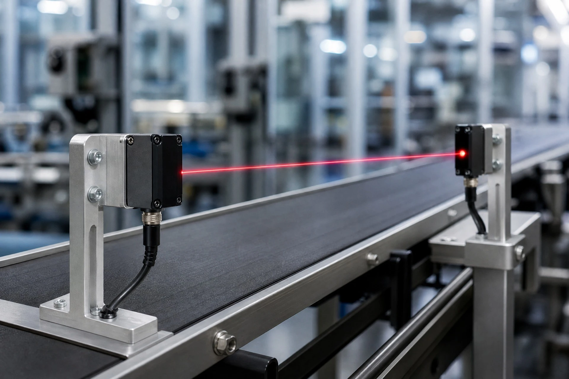
If you have ever spent a frustrating afternoon on a factory floor trying to figure out why your photoelectric sensors are misfiring, you know how annoying mutual interference can be. You set up a row of optical switches to detect parts on a conveyor belt, space them a few inches apart, turn them on, and suddenly they are all talking to each other. One sensor triggers when it shouldn’t, just because the light from its neighbor is bouncing off a metallic surface or spreading too wide.
It is a classic headache in photoelectric sensor design. We call this problem optical crosstalk, or simply cross-talk, and it can completely ruin the reliability of your automated system. Many engineers try to fix this with fancy software filtering, polarization filters, or by sequentially pulsing the emitters. But let’s be honest: those solutions add cost, complexity, and latency.
What if you could solve the problem physically at the source?
The easiest and most reliable way to tackle this is by upgrading your light source. By swapping out your generic wide-angle LEDs for a high-quality narrow beam emitter, you can focus your optical path, eliminate crosstalk, and vastly improve your system’s anti-interference capabilities.
In this guide, we are gonna look at how a narrow beam emitter works, do some simple math to show you the physical difference, and show you how to optimize optical switch systems without tearing your hair out.
What is Crosstalk and Why Does Your Choice of Narrow Beam Emitter Matter?
Before we talk about solutions, we need to understand why optical switches fail in close proximity. When you design a multi-sensor array, you usually align an emitter with a receiver. But standard light-emitting diodes (LEDs) do not shoot light in a straight, laser-like line. They emit light in a cone.
A typical indicator LED or standard IR LED might have a viewing angle (or beam angle) of 30 degrees, 60 degrees, or even wider. In a single-sensor setup, this wide angle is great because it makes alignment incredibly easy. You do not have to be precise; you just point the emitter roughly toward the photodetector, and it works.
But when you pack multiple sensors together, that wide cone of light becomes a nightmare. When you design an optical switch, picking a narrow beam emitter can save you hours of troubleshooting.
The Sneaky Problem of Wide-Angle LEDs
When light leaves a wide-angle emitter, it spreads out rapidly. This causes two major issues:
- Direct Overlap (Crosstalk): The light cone from Emitter A spreads so wide that it spills over and hits Receiver B, which sits next to Receiver A. Receiver B cannot tell the difference between the light from its own transmitter and the stray light from Emitter A. It registers a false signal.
- Reflective Scattering: Wide-angle light hits surrounding machinery, metal brackets, or shiny conveyor components. This scattered light bounces around and eventually finds its way into adjacent receivers.
If you are trying to build high-density sensor arrays—like those used in package sorting, PCB inspection, or precise position sensing—you simply cannot afford this stray light. This is why choosing a specialized narrow beam emitter is so critical. Instead of wasting energy spraying light in all directions, a narrow beam emitter keeps the beam tightly confined, ensuring that only the intended receiver catches the signal.
Enter the 4-Degree Narrow Beam Emitter for Optical Switch Optimization
When we talk about a narrow beam emitter, we aren’t just talking about a slight reduction in angle. To truly eliminate crosstalk in tight spaces, you need to go much narrower. A 4-degree viewing angle LED is generally the sweet spot for these industrial setups.
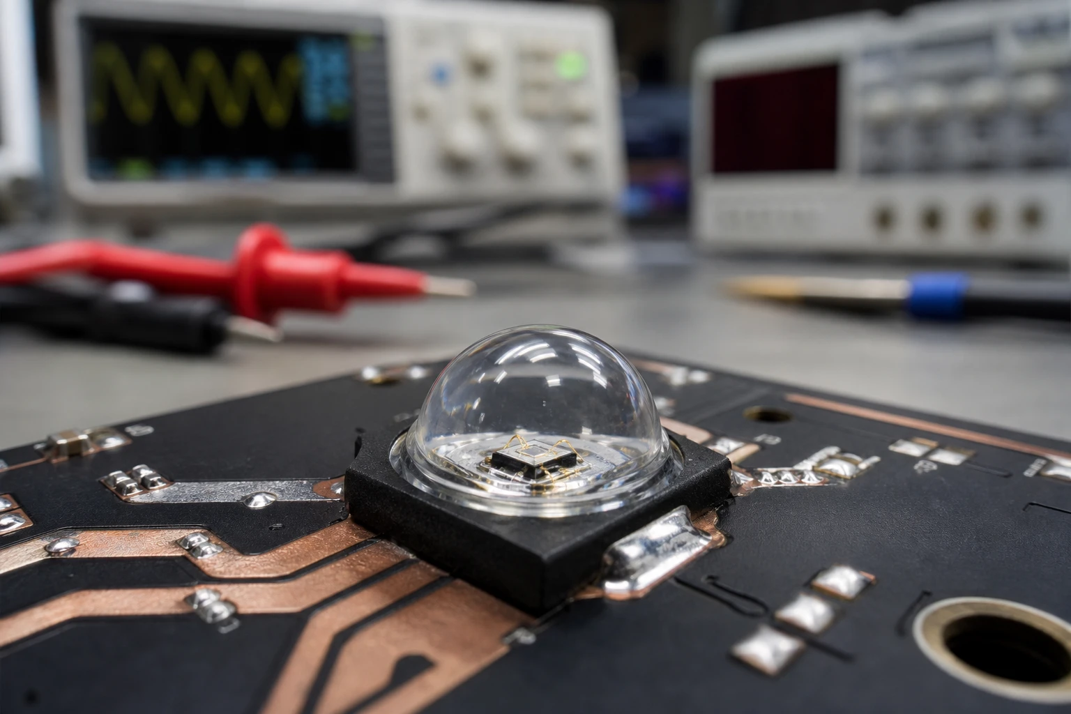
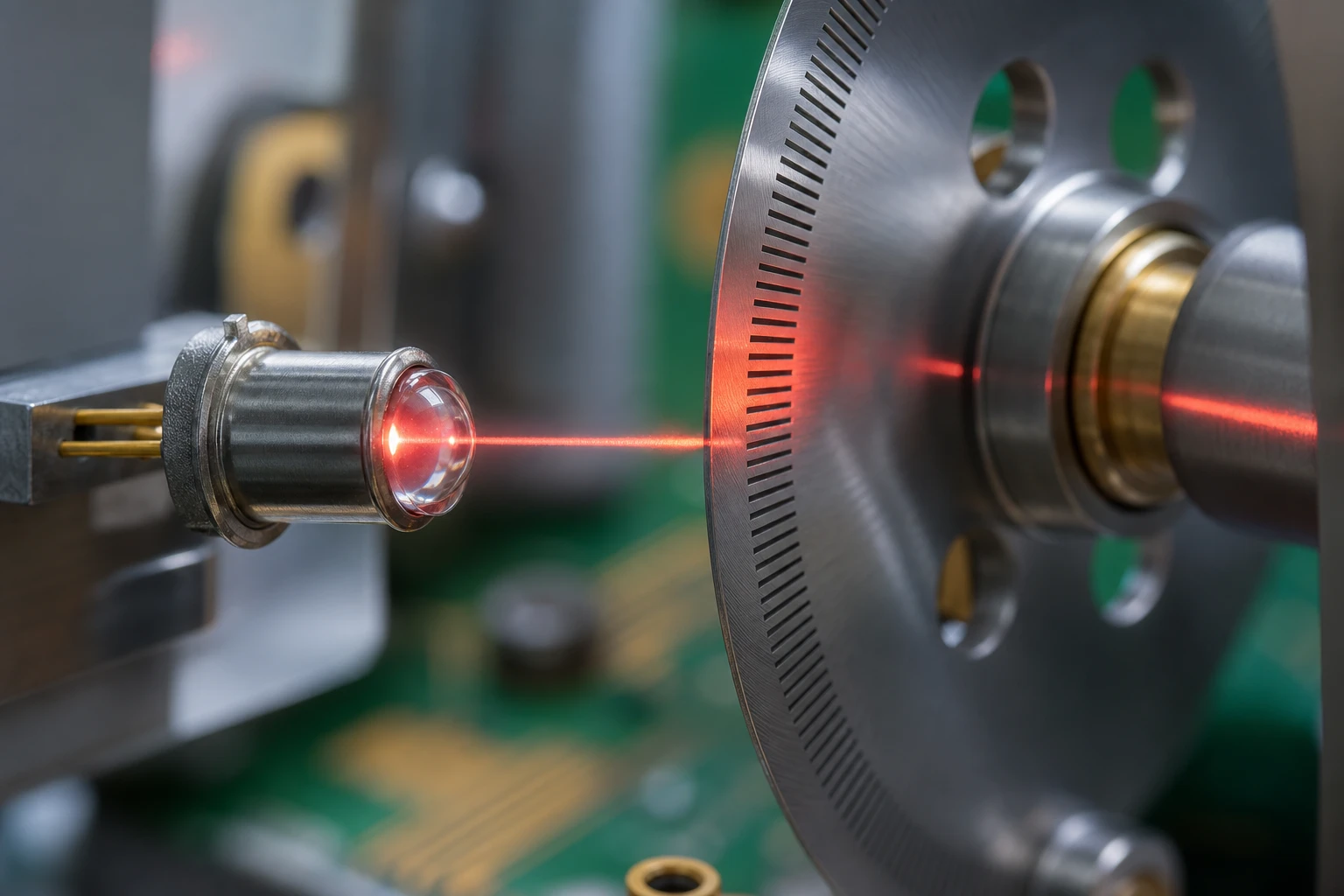
By narrowing down the beam angle to just 4 degrees, you get a highly focused IR LED that behaves almost like a semiconductor laser, but at a fraction of the cost and without the safety hazards associated with laser eye safety regulations.
Why 4 Degrees is the Magic Number for Focused IR LEDs
Why not go even narrower, like 1 or 2 degrees? Well, if you go too narrow, physical alignment becomes incredibly difficult. A tiny vibration in your machine frame could knock the sensor out of alignment and cause a false outage. A 4-degree narrow beam emitter gives you the perfect balance: it is narrow enough to prevent crosstalk at practical working distances (up to a few meters), yet forgiving enough that a technician can align it by hand without needing specialized optical instruments.
Using a high-performance narrow beam emitter completely changes how your system behaves:
- Massive Increase in Optical Power Density: Because all the light energy is concentrated into a small area, the intensity (irradiance) at the receiver is dramatically higher. This gives your sensor a huge “excess gain” margin, letting it cut through dust, steam, and dirt.
- Excellent Anti-Interference: Since the light does not spread to neighboring channels, you do not need to worry about adjacent sensors getting confused.
- Energy Efficiency: You can run the LED at a much lower current while still getting a strong, reliable signal at the receiver. This extends the lifetime of your components and keeps power consumption low.
If you are looking for high-quality components to implement this in your next project, you can browse through a wide range of specialized light source products that offer these narrow viewing angles.
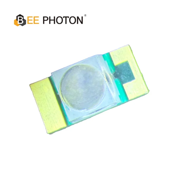
NIR-LED E850-25-001-L20
Der E850-25-001-L20 ist ein Hochleistungs 855nm NIR-LED entwickelt für anspruchsvolle industrielle Anwendungen. Hergestellt von Bee Photon, ist dieses Infrarotstrahler hat einen engen Abstrahlwinkel von 20 Grad und liefert eine hohe Strahlungsintensität von 25 mW/sr, die für Präzisionsmessungen geeignet ist. Das robuste Design sorgt für hohe Zuverlässigkeit und gleichbleibende Leistung über einen weiten Betriebstemperaturbereich.
The Simple Physics: Calculating Beam Spot Sizes with a Narrow Beam Emitter
Let’s do some quick, practical math to see why a narrow beam emitter is so superior. You do not need a degree in optical physics or complex software simulation to understand this. Using a narrow beam emitter changes the math entirely.
To find out how wide your light beam will be at a certain distance, you can use a simple geometric formula:
Spot Size Diameter = 2 * d * tan(theta / 2)
Wo:
dis the distance between the emitter and the receiver (in millimeters or inches).thetais the viewing angle of your light source (in degrees).
Let’s compare a standard 30-degree LED against a 4-degree narrow beam emitter at a typical working distance of 1000 mm (1 meter).
Let’s Do the Math
Case 1: Standard 30-Degree LED
Distance (d) = 1000 mmViewing Angle (theta) = 30 degreestheta / 2 = 15 degreestan(15 Grad) = 0,2679
Spot Size Diameter = 2 * 1000 * 0.2679 = 535.8 mm
At 1 meter away, the light beam from a standard LED has spread to a massive 53.6 centimeters (over 21 inches) wide! If you have adjacent sensors spaced 100 mm (10 cm) apart, this beam will easily cover five or six neighboring receivers. No wonder your sensors are constantly crosstalking!
Case 2: 4-Degree Narrow Beam Emitter
Distance (d) = 1000 mmViewing Angle (theta) = 4 degreestheta / 2 = 2 degreestan(2 Grad) = 0,0349
Spot Size Diameter = 2 * 1000 * 0.0349 = 69.8 mm
With a 4-degree narrow beam emitter, the spot diameter is significantly smaller. At the exact same 1-meter distance, the beam from your narrow beam emitter is only 7 centimeters (under 2.8 inches) wide. If your adjacent sensors are spaced 100 mm apart, there is absolutely zero overlap. This means you can place your adjacent sensors much closer together without worrying about light from one narrow beam emitter bleeding into another sensor’s zone.
The Power Density Bonus
It gets even better. Because the light is focused into a much smaller area, the irradiance (light intensity per unit area) increases exponentially.
The area of a circle is calculated as:
Area = pi * (Diameter / 2)^2
Let’s look at the spot areas for both cases:
- Standard 30-Degree LED Spot Area:
pi * (267.9)^2 = 225,456 square millimeters - 4-Degree Narrow Beam Emitter Spot Area:
pi * (34.9)^2 = 3,826 square millimeters
Now, let’s divide the wide area by the narrow area:
225,456 / 3,826 = 58.9
This means that for the exact same amount of optical power emitted by the chip, the narrow beam emitter delivers almost 59 times more light intensity to the center of the receiver compared to a 30-degree LED!
This massive increase in power density means your sensor can operate reliably in harsh, dusty environments where standard sensors would fail. It also means you can turn down the LED driving current. Running your LED at 10mA instead of 50mA keeps it running cool, which prevents the thermal degradation that slowly kills infrared emitters over time.
How to Upgrade Your Photoelectric Sensor Design Using a Narrow Beam Emitter
To successfully optimize optical switch systems, you can’t just drop a narrow beam emitter into your existing circuit and call it a day. While integrating a narrow beam emitter into your photoelectric sensor design is straightforward, you have to pay attention to a few physical details. Since the beam is much tighter, minor mistakes in mounting or lens alignment can cause issues.
Selecting the Right Narrow Beam Emitter and Receiver Pair
Die narrow beam emitter must be paired with an appropriate photodiode or phototransistor. Here are some of the practical design decisions you’ll face:
- Wavelength Matching: Make sure your narrow beam emitter matches the peak sensitivity of your photodiode. Most industrial optical switches run at 850nm or 940nm (infrared) to avoid interference from visible ambient light. 850nm is slightly visible as a faint red glow, which can help with manual alignment. 940nm is completely invisible.
- Aperture Control: Sometimes, a tight emitter isn’t enough because highly reflective surfaces can still scatter light back into the receiver. Adding a physical aperture or a small slit in front of your photodiode can help narrow down the receiver’s field of view to match your narrow beam emitter.
- Mounting Rigidity: Because your beam is narrow, you need a rigid mounting bracket. If your sensor is mounted on a flimsy piece of sheet metal that vibrates when the machine runs, your light beam will dance all over the place, causing intermittent signal drops. Use solid aluminum or thick plastic brackets to keep everything locked in place.
If you use a high-quality narrow beam emitter, you can often skip complex electronic filtering, which keeps your hardware costs low and your system response speeds lightning-fast. When sourcing parts, look for specialized narrow beam emitter options and consult with specialists through the main BeePhoton website, where you can look at different packages and specs that fit your specific mechanical constraints.
Comparison: Standard Wide-Angle LED vs. Narrow Beam Emitter
To help you visualize the trade-offs, let’s put these two technologies side-by-side. While a wide-angle light source has its place in simple, single-channel devices, a narrow beam emitter is almost always the superior choice for high-density, multi-sensor industrial applications. Looking at the table, it is easy to see why a narrow beam emitter wins in crowded industrial setups.
| Parameter | Standard Wide-Angle LED (30 degrees) | Narrow Beam Emitter (4 degrees) |
|---|---|---|
| Beam Spread at 1 Meter | ~536 mm (Very Wide) | ~70 mm (Tightly Focused) |
| Crosstalk / Interference Risk | Extremely High in Multi-Sensor Arrays | Virtually Non-Existent |
| Relative Light Intensity at Receiver | 1x (Baseline) | ~59x (Highly Concentrated) |
| Alignment Difficulty | Very Low (Plug-and-play) | Moderate (Requires solid mounting) |
| Sensitivity to Dust / Dirt | Mäßig bis hoch | Low (High excess gain cuts through grime) |
| Stromverbrauch | High (Needs high drive current for distance) | Low (Focused beam saves energy) |
| Best Suited For | Single, isolated sensors, indicator lights | Dense sensor grids, conveyor lines, long-range switches |
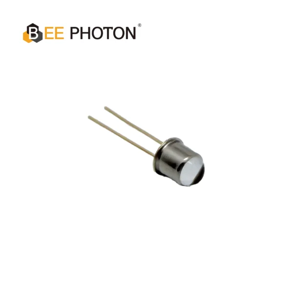
NIR-LED E850-180-201L4
Die E850-180-201L4 ist eine leistungsstarke 850nm NIR-LED für die industrielle Präzisionsmessung entwickelt. Hergestellt von Bienen-Photon, Dieser Infrarot-Strahler ist auf hohe Leuchtkraft und außergewöhnliche Stabilität ausgelegt und damit die ideale Lichtquelle für anspruchsvolle Automatisierungsumgebungen.
Case Study: Fixing a High-Speed Packaging Line with a Narrow Beam Emitter
Let’s look at a real-world example of how a narrow beam emitter can save a project from disaster, which is where a narrow beam emitter came to the rescue.
An automated logistics facility was running a high-speed sorting line. They had a series of photoelectric sensors mounted along a metal rail, spaced just 80 mm apart. These sensors were supposed to detect the exact position of passing cardboard boxes so a pneumatic pusher could slide them into the correct bins.
The Problem
The system was originally built using standard 30-degree IR LEDs as the transmitters. As soon as the line went live, the operators noticed a massive number of sorting errors. The pneumatic pushers were firing at the wrong times, crushing boxes and jamming the line.
After some diagnostic testing with an oscilloscope, the engineering team realized that light from Emitter 1 was scattering off the glossy surface of the packaging tape on the boxes and bouncing straight into Receiver 2. This optical crosstalk made the controller think Box 2 had arrived early, triggering the pusher prematurely.
They tried to solve this by adding cardboard barriers between the sensors, but the vibrations of the conveyor kept knocking the barriers loose, and they quickly accumulated dust, which blocked the sensors entirely.
The Fix
The team decided to solve the problem at the hardware level. They replaced the standard wide-angle transmitters with a custom 4-degree narrow beam emitter from the BeePhoton catalog.
Because the new narrow beam emitter kept the light focused in a tiny 70 mm spot over the 1-meter width of the conveyor, the stray light hitting the shiny packaging tape was drastically reduced. Any minor reflection that did occur was way too weak to trigger the adjacent receivers because the light did not spread outward.
The project showed that a narrow beam emitter not only stops crosstalk but also improves the signal-to-noise ratio. With the new narrow beam emitter installed, the system worked without a single false trigger.
The Results
The upgrade was an instant success:
- Zero Crosstalk: The optical interference between adjacent channels dropped by more than 98%.
- Increased Line Speed: Because the sensors were no longer misfiring, the plant was able to increase the conveyor belt speed by 15%, increasing daily package throughput.
- Maintenance Drop: The high optical density of the narrow beam emitter meant the sensors could tolerate a heavy layer of cardboard dust without losing their signal, reducing the cleaning schedule from once a day to once a month.
This project proved that spending a tiny bit more on a high-quality narrow beam emitter upfront can save tens of thousands of dollars in downtime and ruined inventory down the road.
Step-by-Step Guide: Integrating a Narrow Beam Emitter in Your Next Build
If you are ready to integrate a narrow beam emitter into your next design, here is a simple, no-nonsense guide to getting your system up and running.
Step 1: Choose Your Optics and Wavelength
Choose a narrow beam emitter with a 4-degree or 5-degree viewing angle. If you are working over very long distances (e.g., over 5 meters), you might want to look into an ultra-narrow 2-degree option. Choose 850nm if you want a tiny bit of visible red light to help you align the system, or 940nm if you need it to be completely invisible.
Step 2: Design a Rigid Mount
Align your narrow beam emitter precisely with the receiver. Do not mount your transmitter on flimsy brackets. A tight beam means that even a 1-degree tilt in your bracket can throw the light off-target. Use milled aluminum brackets, robust 3D-printed mounts, or secure sheet metal with dual-point fastening to ensure your optical axis stays locked.
Step 3: Run the Calculations for Spacing
Use the formula we discussed earlier to calculate the spot size at your specific distance. Make sure your sensor pitch (the distance between adjacent sensors) is wider than the beam spot diameter. This guarantees that your narrow beam emitter will never spill light into the neighboring receiver.
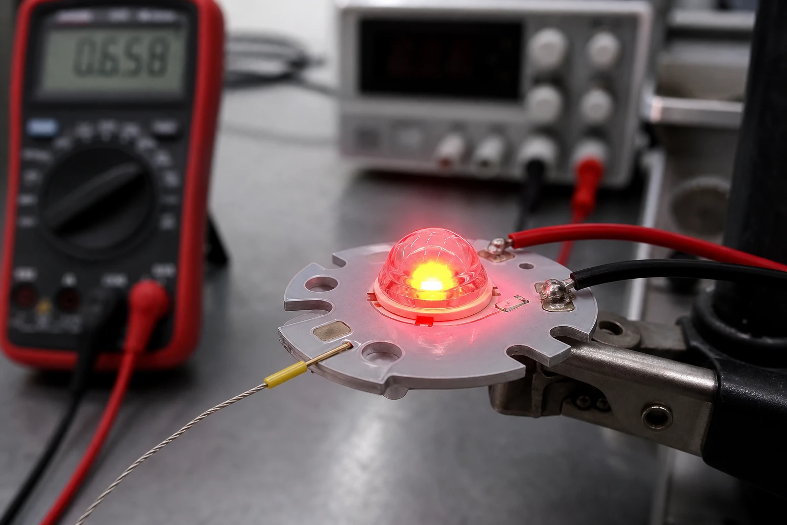
Step 4: Adjust the Drive Current
Test your narrow beam emitter under ambient light conditions. Because a narrow beam emitter concentrates light so efficiently, you probably do not need to run it at its maximum rated current. Start by setting your LED driver to a low current (e.g., 5mA to 10mA) and check if the receiver triggers reliably. If it does, keep it there! Running the LED at a lower current reduces heat, prevents degradation, and ensures your system will run smoothly for years.

Lichtquelle LED-Serie E850-30-101
Die E850-30-101 ist ein hochstabiler 850nm-Infrarotstrahler im robusten 3mm-Dual-Inline-Package-LED-Format für einfache Leiterplattenmontage und überragende Haltbarkeit. Mit einem schmalen Abstrahlwinkel von 20° und einer Strahlungsintensität von 30 mW liefert diese Dual In-line Package LED eine präzise und helle Leistung und ist damit die ideale Lichtquelle für optische Schalter, industrielle Sensorik und anspruchsvolle Automatisierungsanwendungen.
Frequently Asked Questions About Narrow Beam Emitters and Optical Switches
Q1: How do I align a 4-degree narrow beam emitter?
Aligning a narrow beam emitter is definitely more challenging than aligning a wide-angle light source. The easiest trick is to temporarily run a higher current through an 850nm narrow beam emitter so you can see the faint red dot on a piece of paper placed in front of your receiver. If you are using an invisible 940nm wavelength, you can use a cheap smartphone camera (most of them don’t have strong IR filters on the front-facing camera) or an infrared detector card to see exactly where the beam is pointing.
Q2: Can a narrow beam emitter completely eliminate the need for multiplexing?
Yes, in many cases a narrow beam emitter is enough to solve the problem physically. Multiplexing (turning your sensors on and off one by one so they don’t interfere) is a great software trick, but it slows down your sampling rate and increases response time. If you use a 4-degree narrow beam emitter and keep your sensor spacing wider than your beam spot size, you physically eliminate the light overlap. This means all your sensors can run continuously at maximum speed, giving you the fastest possible response time.
Q3: Will a narrow beam emitter work with standard photodetectors?
Absolutely. A narrow beam emitter works with any standard photodetector, phototransistor, or receiver chip that is sensitive to its specific wavelength (usually 850nm or 940nm). It is just a standard infrared LED chip housed in a highly optimized, molded lens package.
Q4: What is the maximum distance I can achieve with a narrow beam emitter?
Weil ein narrow beam emitter concentrates light, you can achieve much greater distances than with standard LEDs. At the same operating current, a 4-degree narrow beam emitter can easily reach distances of 5 to 10 meters in through-beam configurations, whereas a standard 30-degree LED would struggle to maintain a reliable signal past 1.5 meters due to beam divergence and power loss.
Conclusion: Get Started with a Narrow Beam Emitter Today
Let’s face it: struggling with optical crosstalk and sensor interference is a massive waste of time. While software filters and complex electronic modulation can help, they are ultimately just band-aids on a physical problem.
Investing in a narrow beam emitter is the simplest, most reliable way to optimize optical switch performance. By adopting a high-performance narrow beam emitter, you get a tighter beam, zero neighboring interference, massive excess gain, and rock-solid reliability—even in the dustiest industrial environments.
If you are tired of dealing with false triggers and want to build a truly robust photoelectric sensor array, we’ve got you covered. At BeePhoton, we design and manufacture high-performance light source products specifically tailored for demanding optical applications. Whether you need a standard 4-degree focused LED or a custom optical solution, our team of experts is ready to help you find the perfect fit.
Don’t let optical crosstalk slow down your production line. Head over to our Kontaktseite oder schreiben Sie uns eine E-Mail an info@photo-detector.com to request a quick quote, grab some product samples, or chat about your specific sensor design.