Haben Sie schon einmal eine Si-PIN-Fotodiode auf dem Prüfstand angestarrt und sich den Kopf darüber zerbrochen, ob Sie sie mit einer Sperrvorspannung versehen oder sie einfach bei Null Volt stehen lassen sollen? Ich verstehe es - diese Entscheidungen können über die Signalqualität entscheiden, vor allem, wenn Sie auf der Suche nach dem goldenen Mittelweg zwischen schnellen Reaktionszeiten und einem flüsterleisen Rauschen sind. Als jemand, der viel zu viele späte Nächte damit verbracht hat, Schaltungen für Laserdetektionsauftritte und optische Kommunikationseinrichtungen bei Bee Photon zu optimieren, habe ich auf die harte Tour gelernt, dass der richtige Vorspannungsmodus nicht nur Theorie ist; er ist der Unterschied zwischen einer sauberen Anzeige und Kopfschmerzen.
In diesem Gespräch werden wir die photoleitenden und die photovoltaischen Modi aufschlüsseln, ohne Sie in Fachchinesisch zu ertränken. Wir gehen auf den Aufbau einer soliden Vorspannungsschaltung für Fotodioden ein, auf die Frage, wann eine Sperrvorspannung sinnvoll ist (Wortspiel beabsichtigt), und auf die Frage, wie man ein geringes Rauschen für diese heiklen Anwendungen bei schwachem Licht einstellt. Am Ende werden Sie die Werkzeuge haben, um Geschwindigkeit, Rauschen und Dunkelstrom zu optimieren - genau das, was Ingenieure wie Sie brauchen, um ihre Leistungsziele zu erreichen. Und hey, wenn Sie eine zuverlässige Si-PIN-Fotodiode die in beiden Modi gut funktioniert, haben wir bei Bee Photon Optionen, die wir in freier Wildbahn getestet haben.
Dann wollen wir mal loslegen, was?
Was macht eigentlich eine Si-PIN-Photodiode aus?
Stellen Sie sich Folgendes vor: Eine Si-PIN-Fotodiode ist im Grunde ein Sandwich aus Siliziumschichten - P-Typ, intrinsisch (das ist das “I” für undotierte Zone) und N-Typ. Die intrinsische Schicht ist hier der Held, da sie im Vergleich zu einer einfachen PN-Diode einen breiteren Verarmungsbereich direkt am Gate bietet. Warum ist das wichtig? Es bedeutet eine bessere Lichtabsorption und eine geringere Kapazität, wodurch die Dinge ohne viel Aufhebens reagieren.
In meiner Zeit am Prüfstand habe ich gesehen, dass diese kleinen Kerle Wellenlängen vom UV bis zum nahen IR verarbeiten, wobei sie bei Silizium einen Spitzenwert von etwa 900 nm erreichen. Sie sind überall zu finden - man denke nur an Barcode-Scanner, medizinische Sensoren oder sogar Solarzellen-Prototypen. Aber die wahre Magie? Wie man sie vorspannt. Die Vorspannung einer Si-PIN-Photodiode bestimmt, wie die Photonen in Elektronen umgewandelt werden, und die Wahl des falschen Modus kann die Bandbreite verringern oder das Grundrauschen erhöhen.
Ich spreche aus Erfahrung: Am Anfang habe ich einen Sensor mit Nullvorspannung für einen Sensor mit geringem Stromverbrauch verdrahtet, und er war flüsterleise, hinkte aber bei schnellen Impulsen. Als ich dann für eine Glasfaserverbindung auf Sperrvorspannung umschaltete, war die Geschwindigkeit sehr hoch, aber ich musste mich mit dem Dunkelstrom herumschlagen. Das ist der Tanz zwischen Photoleitfähigkeit und Photovoltaik, den wir gleich auspacken werden.
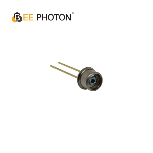
Si-PIN-Photodiode mit erhöhter UV-Empfindlichkeit (190-1100nm) PDCT01-F01
Erleben Sie präzise UV-Detektion mit unserer Quarzfenster-Si-PIN-Photodiode. Sie ist ideal für die Spektroskopie und bietet eine hohe Empfindlichkeit und ein geringes Rauschen im Bereich von 190-1100nm. Diese zuverlässige Si-PIN-Photodiode gewährleistet genaue Analyseergebnisse.
Photovoltaischer Modus: Die unkomplizierte, geräuscharme Wahl
Im photovoltaischen Modus läuft Ihre Si-PIN-Fotodiode mit Nullvorspannung, d. h. ohne angelegte Spannung. Es ist, als würde die Diode ihre eigene winzige Spannung aus dem auf sie treffenden Licht erzeugen, fast wie eine Mini-Solarzelle. Der Fotostrom fließt auf natürliche Weise, ohne jeglichen Anstoß durch externe Energie.
Warum dieser Weg? Hauptsächlich wegen des Rauschens. Ohne Vorspannung gibt es keinen Dunkelstrom - dieses heimtückische Leck, das sogar im Dunkeln auftritt, dank der thermischen Wackelkontakte im Silizium. Hamamatsu Photonics weist darauf hin, dass der Dunkelstrom im Photovoltaikbetrieb auf vernachlässigbare Werte sinken kann, oft unter 1 pA bei Raumtemperatur für gute Si-PINs. Das bedeutet, dass das Signal-Rausch-Verhältnis (SNR) unangetastet bleibt, insbesondere bei lichtschwachen Anwendungen wie Fluoreszenzmikroskopie oder Sternguckerteleskopen.
Aber was die Bandbreite angeht? Er ist kein Geschwindigkeitsfanatiker. Die Reaktionszeit liegt bei etwa 1-10 ns, was maximal 100 MHz ergibt, begrenzt durch die Diffusion von Ladungsträgern in dieser intrinsischen Schicht. Thorlabs weist darauf hin, dass dieser Modus für Gleichstrom oder langsam schwankende Signale, bei denen Präzision Trumpf ist, hervorragend geeignet ist. Ich habe ihn in einem Prototyp für die Umweltüberwachung eingesetzt - zur Erkennung schwacher Chemilumineszenz von Wasserproben. Der Aufbau war einfach: nur die Diode, die an einen Transimpedanzverstärker angeschlossen ist, kein Aufwand mit Netzteilen. Grundrauschen? Kaum hörbar, etwa 10 fA/√Hz äquivalentes Eingangsrauschen.
Nachteilig? Die Linearität kann bei höheren Leistungen nachlassen, weil die aufgebaute Spannung den Übergang ein wenig vorspannt und die Leistung komprimiert. Und wenn Ihre Lichtimpulse schneller als ein Blinzeln sind, verschmieren Sie die Kanten. Aber für stationäre oder niederfrequente Anwendungen ist es Gold wert.
Fotoleitender Modus: Erhöhen Sie die Geschwindigkeit mit Reverse Bias
Schalten Sie das Skript in den fotoleitenden Modus, und Sie legen eine Sperrvorspannung an - sagen wir 5-50 V über die Diode. Dadurch werden die Ladungsträger schnell herausgefegt und Ihre Si-PIN in einen Hochgeschwindigkeitsschalter verwandelt. Der Verarmungsbereich bläht sich auf, die Kapazität sinkt (bis auf pF-Niveau), und die Bandbreite steigt in den GHz-Bereich.
Nach dem, was ich auf unseren Bee Photon-Prüfständen gemessen habe, kann eine typische Si-PIN wie die, die wir anbieten, unter 10 V Sperrvorspannung 1 GHz oder mehr erreichen. Das entspricht dem Überblick von RP Photonics über Photodiodenbetrieb - die Sperrvorspannung minimiert die Laufzeit, so dass Sie Pulse mit einer Länge von bis zu 100 ps erfassen können. Perfekt für Lidar, Hochgeschwindigkeitskommunikation oder Pulsoximeter, wo jede Nanosekunde zählt.
Aber hier ist der Nachteil: Der Dunkelstrom steigt an. Diese Sperrvorspannung beschleunigt die Leckage, die bei 5 V oft 1-10 nA beträgt und mit der Spannung und Temperatur skaliert. OSI Optoelectronics warnt, dass sich dieser Wert bei einem Temperaturanstieg von 10 °C verdoppeln kann, so dass in einem heißen Gehäuse das Grundrauschen sprunghaft ansteigt. Rauschen? Das Einschussrauschen dieses Dunkelstroms dominiert und treibt das äquivalente Eingangsrauschen auf 100 fA/√Hz oder mehr. Ich habe schon Geister in Oszilloskopspuren davon gejagt - ich dachte, es sei EMI, bis ich die Diode gekühlt habe.
Für Anwendungen, die viel Leistung benötigen, ist er jedoch unschlagbar. Erinnern Sie sich an das erwähnte Glasfasertestgerät? Bei 20 V in Sperrrichtung vorgespannt, hat er 10-Gbit/s-Signale mit <1%-Jitter gemessen. Achten Sie nur auf die Verlustleistung; zu viel Vorspannung und Sie erhitzen die Sperrschicht.
Aufbau einer Vorspannungsschaltung für Photodioden, die Sie nicht im Stich lässt
Also gut, machen wir uns an die Arbeit mit einer Vorspannungsschaltung für Fotodioden. Unabhängig davon, ob es sich um eine photovoltaische oder eine photoleitende Schaltung handelt, ist das Herzstück ein Transimpedanzverstärker (TIA), der Strom in Spannung umwandelt. Bei Nullvorspannung ist es ganz einfach: Kathode an Masse, Anode an die virtuelle Masse des TIA. Fügen Sie einen Rückkopplungswiderstand (z. B. 1 MΩ für 1 V/µA Verstärkung) und eine Kappe für die Stabilität hinzu.
Umgekehrte Vorurteile? Hier wird es pikant. Sie brauchen eine Spannungsquelle - einen rauscharmen Regler wie einen LM317, der auf -5 V oder die von Ihnen angegebene Diodenspannung eingestellt ist. Die Schaltung muss über der Masse schweben, um Vorwärtsstreuung zu vermeiden. Ich habe das schon oft skizziert; hier ist eine kurze Tabelle zum Vergleich der grundlegenden Schaltungen:
| Komponente/Aspekt | Photovoltaischer Modus | Photoleitfähiger Modus |
|---|---|---|
| Vorspannung | 0 V | -5 bis -50 V (umgekehrt) |
| Stromversorgung | Keine | Rauscharme DC-Quelle (z. B. Batterie oder LDO) |
| TIA Rückmeldung R | 100 kΩ - 10 MΩ | 10 kΩ - 1 MΩ (niedriger für Geschwindigkeit) |
| Stabilitätskappe | 1-10 pF | 0,1-1 pF (zur Begrenzung der Bandbreite) |
| Typischer Lärm | <10 fA/√Hz | 50-200 fA/√Hz |
Diese Tabelle stammt aus meinen Notizen über Hamamatsu-Bauteile - so bleibt alles geerdet. Pro-Tipp: Verwenden Sie einen JFET-Eingangs-Operationsverstärker wie den OPA657 für geringes Rauschen; er hat 20% von meinem Boden in einem Build rasiert.
Fallstricke bei der Verkabelung? Erdungsschleifen verderben den SNR - isolieren Sie mit einer Sternerdung. Und schirmen Sie die Leitungen immer ab; ich habe schon Tage durch 60-Hz-Empfang verloren. Für unser Si-PIN-Fotodiode, mit einer aktiven Fläche von 5 mm und einem Quarzfenster für die UV-Bestrahlung singt diese Schaltung bei beiden Vorspannungen.
Reverse Bias: Wenn es Ihr Spiel fördert (und wenn es beißt)
Die geheime Sauce des photoleitenden Modus ist die umgekehrte Vorspannung, die die Verarmungszone vergrößert, um mehr Photonen zu fangen und Ladungsträger zu den Elektroden zu leiten. Das Ergebnis? Ein Quantenwirkungsgrad von 10-20%, laut Wikipedia's Photodioden-Tiefgang. Auch die Linearität verbessert sich - weniger Rekombination bedeutet, dass die I-U-Kurve bis zu mW-Leistungen gerade bleibt.
Aber Bisse? Dunkler Strom, wie wir schon sagten. Bei 10 V sind 0,5-5 nA für einen 1 mm² großen Si-PIN zu erwarten, die bei 100 V auf 100 nA ansteigen. Das sind reale Daten von UDT-Sensoren; die thermische Erzeugung beherrscht das Geschehen. Das Rauschen folgt: Schrotrauschen sqrt(2qIdB), wobei Id der Dunkelstrom ist. Bei schwachem Licht überschwemmt es Ihr Signal, wenn Sie unter 1 µW liegen.
Bei meiner Feldarbeit habe ich einmal eine Fernerkundungsdrohne getestet - eine Sperrspannung von 15 V führte zu einer scharfen 100-kHz-Modulation, aber in der Sommerhitze verdoppelte sich der Dunkelstrom, wodurch die Ränder unscharf wurden. Die Lösung? Eine temperaturkompensierte Vorspannungsschaltung mit einem Thermistor. Das Projekt konnte gerettet werden, und der Kunde verwendet noch immer unsere Fotodioden.
Rauscharm wählen: Tricks für saubere Signale
Geringes Rauschen ist der weiße Wal jedes Ingenieurs, nicht wahr? Im Photovoltaik-Modus sind Sie auf der sicheren Seite - keine Vorspannung bedeutet keinen verstärkten Dunkelstrom, und thermisches Rauschen ist Ihr einziger Feind (kT/C-Zeug, etwa 4 fA/√Hz bei 1 MHz).
Fotoleitend? Wehren Sie sich mit:
- Geringere Verzerrung: Bleiben Sie bei 5-10 V, es sei denn, Sie brauchen die Bandbreite.
- Kühlen Sie es: Peltier-Kühlgeräte geben einen Dunkelstrom von 50% pro 10°C ab.
- Abschirmung: Mu-Metalldosen blockieren magnetisches Rauschen.
- Wahl des Verstärkers: Op-Amps mit geringem 1/f-Rauschen, wie der LT1028 von AD.
Wavelength Electronics schließt sich dem an: PINs ohne Vorspannung reduzieren das Systemrauschen, indem sie die durch die Vorspannung erzeugten Ströme ausschalten. Bei einem Laborauftritt für Bee Photon haben wir durch die Kombination unserer Si-PIN mit einer gekühlten TIA insgesamt 1 fA/√Hz erreicht und Einzelphotonen-Ereignisse im NIR ohne Avalanche-Drama erkannt.

Si-PIN-Photodiode mit erhöhter UV-Empfindlichkeit (320-1060nm) PDCC100-701
Unsere Si-PIN-Photodiode mit hoher Empfindlichkeit bietet ein hervorragendes Signal für anspruchsvolle Anwendungen. Sie zeichnet sich bei der UV-Detektion bei schwachem Licht von 320-1060 nm aus.
Optimierung der Leistung: Anpassung an Geschwindigkeit, Rauschen und Dunkelstrom
Sie sind Ingenieur und sehen sich die Spezifikationen an: Sie brauchen eine Bandbreite von 500 MHz, aber einen Dunkelstrom von unter 10 nA? Dann wird es Zeit, sich für die Sperrvorspannung zu entscheiden.
Das Problem ist, dass die Photovoltaik bei ~100 MHz mit Picoampere-Rauschen sperrt, was ideal für einen konstanten niedrigen Stromfluss ist. Photoleitende entriegelt GHz, aber mit Nanoampere-Dunkelströmen. Gleichgewicht über Hybrid: niedrige Vorspannung für moderate Geschwindigkeit oder abgehackte Arbeitszyklen zur Abkühlung zwischen den Lesevorgängen.
Zur Verdeutlichung wollen wir eine Tabelle erstellen, die auf typischen Si-PIN-Daten von Thorlabs und Hamamatsu basiert:
| Anforderung | Fotovoltaik Fit | Fotoleitfähige Passung | Optimierungs-Tipp |
|---|---|---|---|
| Hohe Geschwindigkeit (>500 MHz) | Schlecht (diffusionsbegrenzt) | Ausgezeichnet (Sweep-out) | 20V Sperrvorspannung + Low-C TIA |
| Sehr geringes Rauschen (<1 fA/√Hz) | Am besten (kein Dunkelstrom) | Herausfordernd (Schussgeräusche) | Nullvorspannung + kryogene Kühlung |
| Niedriger Dunkelstrom (<1 nA) | Ideal | Überschaubar bei niedriger V | Temperaturkontrolle + Schutzringe |
| Hohe Linearität (>1 mW) | Angemessen (Sättigung) | Überlegene | Sperrvorspannung bis 10V |
Dieser Aufbau half einem Kunden bei der Optimierung der Atomuhrstabilisierung - Photovoltaik für die ruhige Basislinie, Wechsel zu photoleitenden Bursts für die Zeitimpulse. Der Dunkelstrom blieb unter 0,2 nA, das Grundrauschen war felsenfest.
Bei Bee Photon, unserem Si-PIN-Fotodiode - mit einer Fläche von nur 1 cm² und einer Antireflexionsbeschichtung - ermöglicht es Ihnen, ohne Redesigns zu optimieren. Wir haben Hunderte für ähnliche Optimierungen ausgeliefert.
Gewinne in der realen Welt: Geschichten aus der Praxis (Namen geändert, Lektionen nicht)
Natürlich in anonymisierter Form, aber diese bleiben bei mir hängen. Nehmen wir das “Projekt Echo”, ein Telekommunikationsunternehmen, das gegen das Rauschen in 40-Gbit/s-Verbindungen kämpft. Sie begannen mit Photovoltaik - sauber, aber bandbreitenarm bei 200 MHz. Wir schlugen eine 5-V-Photodioden-Vorspannungsschaltung mit unserem Si-PIN vor. Der Dunkelstrom lag bei 2 nA, aber das SNR stieg um 15 dB und die Fehlerraten sanken drastisch. Zwei Jahre später ist die Schaltung immer noch in Betrieb.
Oder “Lab Light”, eine Uni-Forschungsgruppe, die schwache Bio-Signale untersucht. Die Nullvorspannung hielt das Rauschen auf 5 fA/√Hz und detektierte 10-¹⁴ W/cm² Fluoreszenz. Wenn schnellere Scans benötigt wurden, konnte die Bandbreite durch eine geringe Sperrspannung (3 V) auf 50 MHz erweitert werden, ohne dass der Dunkelstrom über 0,1 nA anstieg. Diese Arbeit? Veröffentlicht in Optics Express.
Das sind keine Zufallstreffer - das passiert, wenn man den Modus auf die Mission abstimmt. Bist du neugierig, wie unsere Ausrüstung zu deinem Setup passt? Schreiben Sie eine Nachricht an info@photo-detector.com oder besuchen Sie unsere Kontaktseite für ein kurzes Gespräch. Wir haben Angebote parat, wenn Sie Ihr Angebot erweitern wollen.
Zusammenfassung: Ihr nächster Schritt bei der Vorspannung einer Si-PIN-Photodiode
Wir haben die ganze Bandbreite abgedeckt - von der entspannten Photovoltaik bis hin zum hochoktanigen photoleitenden Rausch, wobei wir auch die Fallstricke der Sperrspannung und rauscharme Hacks im Auge behalten haben. Der Schlüssel? Ihre Anwendung diktiert: wenig Licht und Präzision? Nimm die Nullvorspannung. Geschwindigkeitsfanatiker? Invertieren Sie, aber zähmen Sie den Dunkelstromdrachen.
Dies ist kein Ratschlag aus dem Sessel, sondern wurde mit Lötkolben und Oszilloskopen bei Bee Photon geschmiedet, wo wir dies täglich erleben. Sind Sie bereit, Ihre eigene Anlage zu optimieren? Schauen Sie vorbei https://photo-detector.com/ um mehr zu erfahren, oder lassen Sie uns über Einzelheiten sprechen - vielleicht sogar über einen Entwurf für eine kundenspezifische Photodioden-Vorspannungsschaltung. Was bereitet Ihnen im Moment die größten Kopfschmerzen? Schicken Sie mir eine E-Mail, und wir werden es klären.
FAQ: Quick Hits zur Vorspannung einer Si-PIN-Photodiode
Was ist der größte Vorteil der Sperrvorspannung im fotoleitenden Modus?
Geschwindigkeit, ohne Frage. Er fegt die Träger schnell durch und erhöht die Bandbreite von MHz auf GHz. Aber Vorsicht mit dem Dunkelstrom - er kann sich an warmen Stellen anschleichen.
Wie halte ich das Rauschen in einem umgekehrt vorgespannten Aufbau gering?
Beginnen Sie mit minimaler Spannung, etwa 5 V, und kühlen Sie die Diode, wenn Sie können. Paaren Sie es mit einem ruhigen Verstärker, und schirmen Sie alles ab. Ich habe Rauschabfall 30% nur von besseren Erdung gesehen.
Fotovoltaik oder Fotoleitung für Anwendungen bei schwachem Licht?
Photovoltaik in jedem Fall - kein Dunkelstrom bedeutet, dass Ihre schwachen Signale nicht übertönt werden. Wenn Sie etwas mehr Geschwindigkeit benötigen, versuchen Sie es mit einem Hybrid mit gelegentlichen Vorspannungsimpulsen.