Look, designing analog front ends is brutally hard. If you’re a hardware engineer trying to feed real-world optical data into an AI system, you already know the pain. You grab a photodiode, slap a transimpedance amplifier (TIA) next to it, route the traces, and pray. Then you power it up, and your oscilloscope just shows a massive wall of noise. The AI model at the end of your pipeline gets garbage data, and your project stalls.
I’ve been there too many times. Bridging the physical world of light to the digital brains of artificial intelligence requires seriously clean signal processing. Lately, everyone is obsessing over things like Gemini deep thinking and massive language models, but those models are useless if the sensory data feeding them is compromised by terrible hardware design. The software guys just assume the hardware works. We know better.
If you want to simplify your life and actually get clean data into your neural networks, you need to stop building discrete optical front ends. It’s time to heavily rely on integrated photodiode modules.
The Real Problem with Optical Signal Processing
Let’s talk about the physics for a second. When a photon hits your sensor, it generates a tiny, fragile little current. I’m talking microamps, or even nanoamps. This signal is so weak that just looking at it funny seems to introduce electromagnetic interference (EMI).
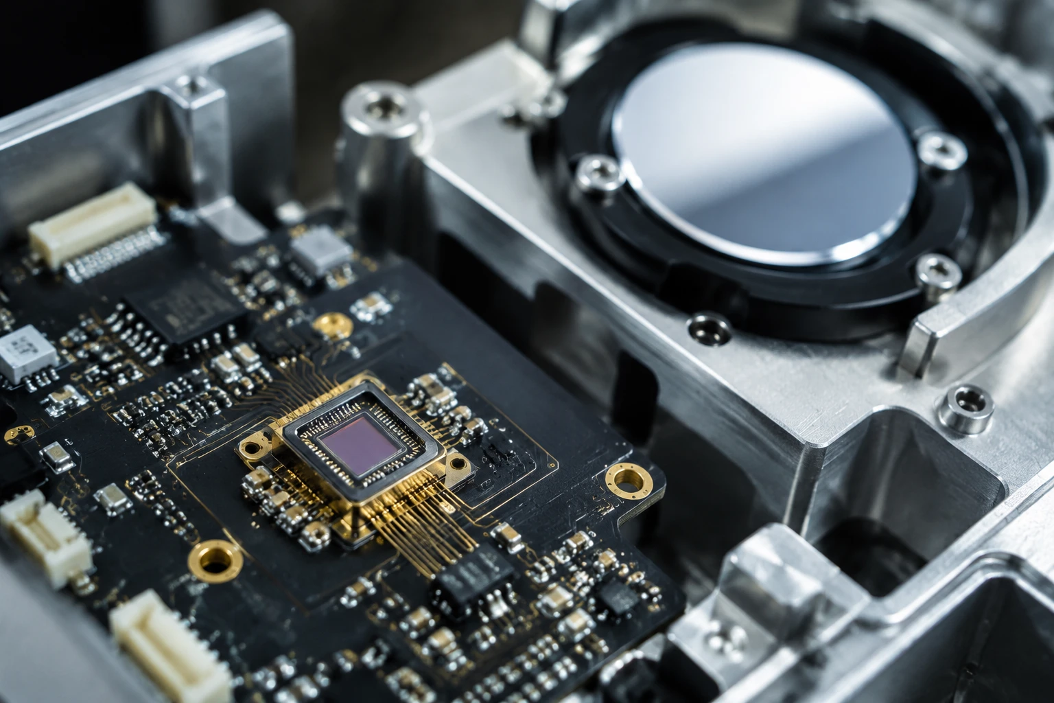
When you build a discrete circuit, you have the photodiode package, the solder pads, the PCB trace, the TIA input pin, and the feedback loop. Every single millimeter of that PCB trace acts like an antenna. It picks up 60Hz hum from the lights, switching noise from your power supply, and whatever your local Wi-Fi router is screaming out.
On top of that, you have parasitic capacitance. The trace itself adds capacitance to the TIA’s inverting input. Let’s look at the basic math of TIA bandwidth (no fancy formatting here, just pure engineering text):
Bandwidth f_3dB = sqrt( GBW / (2 * pi * R_f * C_total) )
Here, GBW is the gain-bandwidth product of your op-amp, R_f is your feedback resistor, and C_total is the total capacitance at the input.
Notice that C_total is in the denominator. When you increase the capacitance by routing a trace on an FR4 board, you crush your bandwidth. You also destroy your phase margin, which leads to peaking and ringing. Your beautiful square wave optical pulse turns into a ringing, oscillating mess. This is exactly why integrated photodiode modules are taking over. By putting the detector and the amplifier in the same hermetically sealed package, C_total drops off a cliff. The distance between the diode and the amp becomes microscopic.
What Actually Are Integrated Photodiode Modules?
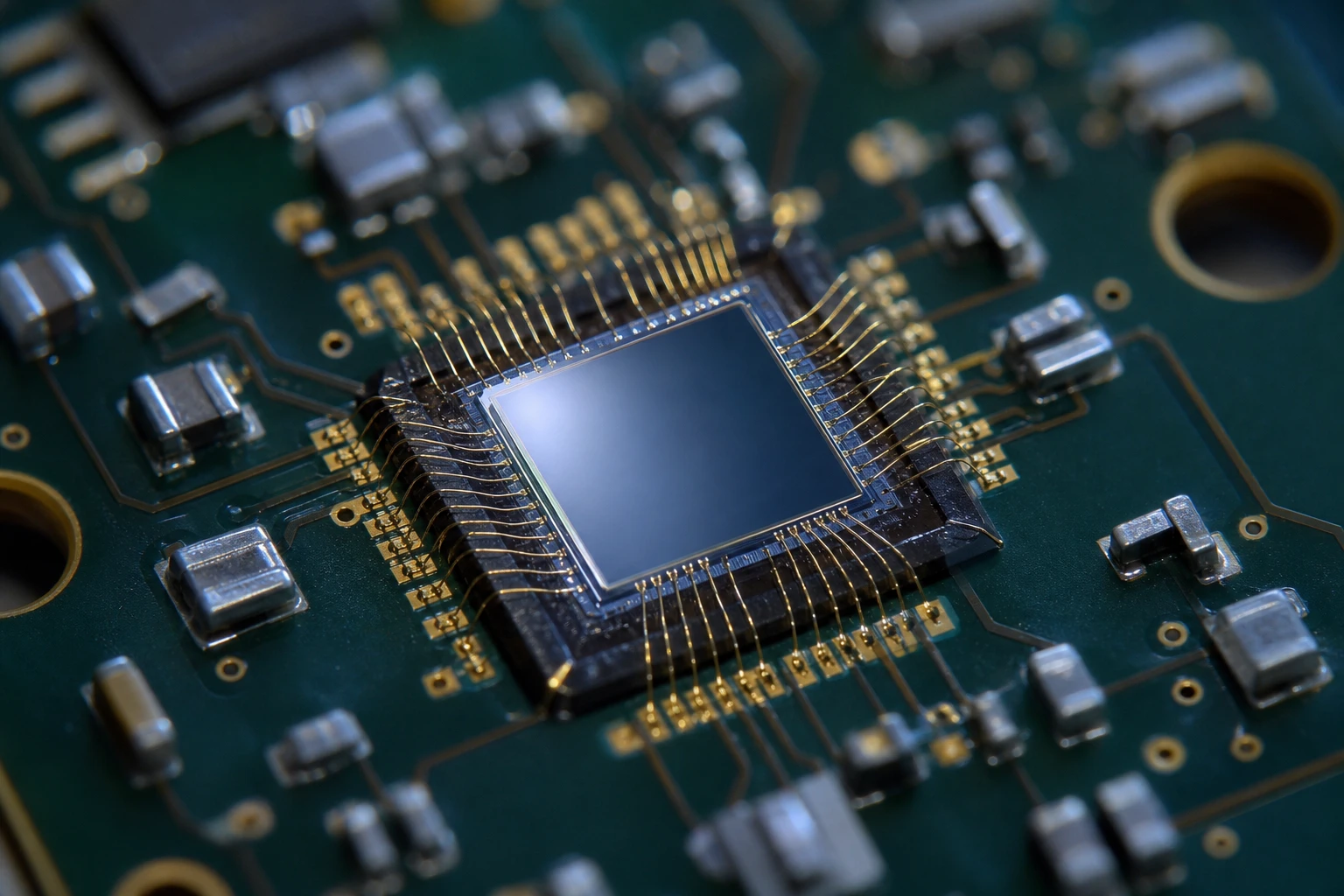
To put it simply, integrated photodiode modules combine the light-sensitive element (usually a silicon or InGaAs diode) and the first stage of amplification into one single component.
Instead of dealing with nanoamps of raw current, these modules output a buffered, low-impedance voltage. You are handing your downstream analog-to-digital converter (ADC) a robust, easy-to-read signal.
For many AI edge devices, especially in machine vision, LiDAR, or biomedical sorting, engineers typically use Si PIN photodiodes for the sensing element. Silicon PIN diodes are fantastic for the visible and near-infrared (NIR) spectrum up to about 1100nm. They have a wide depletion region, which gives them lower capacitance and faster response times compared to standard PN junctions. When you bake these Si PIN diodes directly into integrated photodiode modules, you get lightning-fast response times without the routing nightmare.
A Controversial Take: Discrete Front-Ends Are Dead
I’ll just say it: if you are still trying to route bare photodiodes to separate op-amps on a standard PCB for high-speed AI edge devices, you are wasting your company’s time and money.
I know some old-school RF guys will fight me on this. They love tweaking their guard rings and polishing their teflon standoffs. But in the modern product development cycle, where you need to get an AI-driven hardware product to market in six months, you don’t have time to spin three board revisions just to fix a noise floor issue. Discrete design is obsolete for 90% of commercial AI hardware applications. Integrated photodiode modules give you predictability, and in engineering, predictability is everything.
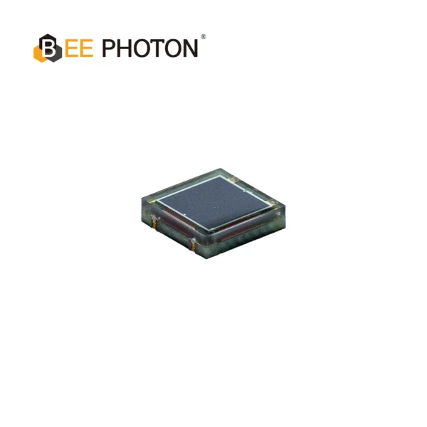
Si PIN Photodiode with NIR sensitivity enchanced (350-1100nm) PDCC34-501
Bee Photon offers a High Stability PIN Photodiode for precise industrial sensing. This NIR enhanced photodiode ensures reliable measurements from 350-1100nm. A top choice for a high stability photodiode.
First-Hand Experience: Speeding Up a Smart Sorting Machine
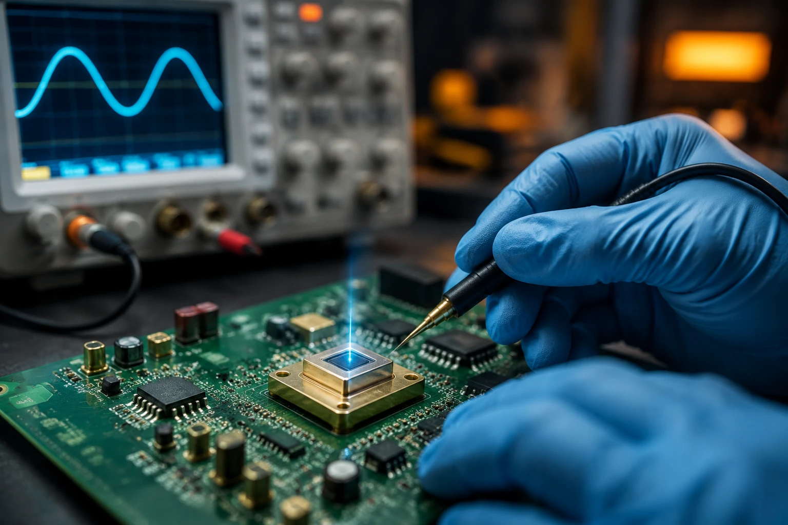
Let me share a story from a recent consulting gig. A client was building a high-speed optical sorting machine for recycling. They were using machine learning to identify plastics based on their optical signatures as they flew down a conveyor belt at 5 meters per second.
Their initial design used discrete avalanche photodiodes (APDs) connected to external TIAs. The system worked on the bench, but the moment they put it on the factory floor, the electrical noise from the massive industrial motors completely swamped their signals. Their AI model’s accuracy dropped to about 40%. It couldn’t distinguish a PET bottle from an HDPE jug because the optical waveform was buried in EMI.
They asked me to look at the board. The routing wasn’t terrible, but it was a discrete layout. The parasitic capacitance of the board was amplifying the high-frequency voltage noise of the op-amp.
We ripped out the discrete front end and dropped in high-bandwidth integrated photodiode modules from BeePhoton. Because the amplifier was shielded inside the module’s metal can, the factory EMI couldn’t touch the high-impedance node.
The result? The noise floor dropped by a factor of 10. The output voltage was crisp. We fed that clean data through a 14-bit ADC and straight into their edge AI processor. The model’s sorting accuracy shot up to 98% almost immediately. We didn’t touch the AI software at all; we just fixed the physical layer using integrated photodiode modules.
The Math: From Photons to AI Volts
Let’s break down the actual conversion process so you know exactly what integrated photodiode modules are doing under the hood.
- Optical Power to Current: When light hits the photodiode, it creates current based on its responsivity (R).
Formula: I_pd = P_optical * R
If you have 10 microwatts of light at 850nm, and the Si PIN diode has a responsivity of 0.5 A/W, your current is:
I_pd = 10uW * 0.5 A/W = 5 microamps (5uA). - Current to Voltage:
The internal TIA inside the integrated photodiode modules converts this current to a voltage using a feedback resistor (R_f).
Formula: V_out = I_pd * R_f
If the internal R_f is 100 kilo-ohms (100k):
V_out = 5uA * 100,000 ohms = 0.5 Volts.
That 0.5V signal is what your ADC reads.
But what about noise? This is where integrated photodiode modules really earn their keep. In a discrete setup, the thermal noise of the resistor (Johnson noise) and the amplifier’s input noise voltage get magnified by the board capacitance.
Thermal noise current of a resistor is calculated as:
I_noise_rms = sqrt( (4 * k * T * Bandwidth) / R_f )
Where ‘k’ is Boltzmann’s constant and ‘T’ is temperature in Kelvin.
Because integrated photodiode modules minimize the capacitance, you can often use a higher R_f to get the same bandwidth. A higher R_f actually improves your signal-to-noise ratio because the signal scales linearly with R_f, while the thermal noise current scales with the square root of R_f. It’s free performance.
Comparing Your Options
Sometimes a table is the best way to see the reality of hardware choices. Here is how integrated photodiode modules stack up against discrete builds.
| Feature | Discrete Photodiode + TIA PCB | Integrated Photodiode Modules |
|---|---|---|
| Parasitic Capacitance | High (1pF to 5pF typical) | Ultra-Low (< 0.2pF typical) |
| EMI Immunity | Poor (Traces act as antennas) | Excellent (Shielded within package) |
| Bandwidth Limits | Restricted by PCB layout | Maximized by internal bonding |
| Time to Market | Slow (Requires multiple PCB respins) | Fast (Plug and play performance) |
| Footprint on PCB | Large | Very Small |
| Cost | Cheaper BOM, higher engineering cost | Slightly higher BOM, zero headache |
As you can see, integrated photodiode modules win on almost every metric that actually matters when you’re trying to ship a product. Yes, the unit cost might be a dollar or two higher, but how much is your engineering time worth? How much does a delayed product launch cost the business?
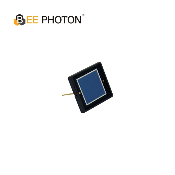
Si PIN Photodiode with low dark current (350-1060nm) PDCD100-101
Upgrade your devices with our Si PIN Photodiode for Optical Measurement. It delivers high accuracy across a 350-1060nm range with minimal dark current. Ideal for various industrial sensing and measurement applications, this high-performance sensor guarantees precision and repeatability.
Feeding the AI: The Gemini Deep Thinking Connection
So how does this hardware tie into the massive AI software trends we are seeing today? You’ve probably heard about Gemini deep thinking and how these advanced algorithms can reason through complex problems.
These AI models are increasingly being deployed at the “edge” – meaning right on the device, rather than in the cloud. Think about autonomous drones, smart medical blood analyzers, or LiDAR-equipped robots. These machines use AI to process their environment in real time.
The AI needs massive arrays of tensor data to make its decisions. If the optical sensors on a drone are feeding noisy, jittery data to the AI because the hardware engineer used cheap discrete photodiodes, the AI’s “deep thinking” will lead to a crash. Garbage in, garbage out.
Integrated photodiode modules act as the perfect translator. They take the analog chaos of photons and package it into a clean, highly linear analog voltage. This voltage is sampled by an ADC, turned into a digital matrix, and fed directly into the neural network. By using integrated photodiode modules, you guarantee that the foundation of your AI’s reality is rock solid.
Choosing the Right Module for Your Project
You can’t just buy any module and expect it to work. You have to match the specs to your specific application. Here’s how I usually break it down for my clients:
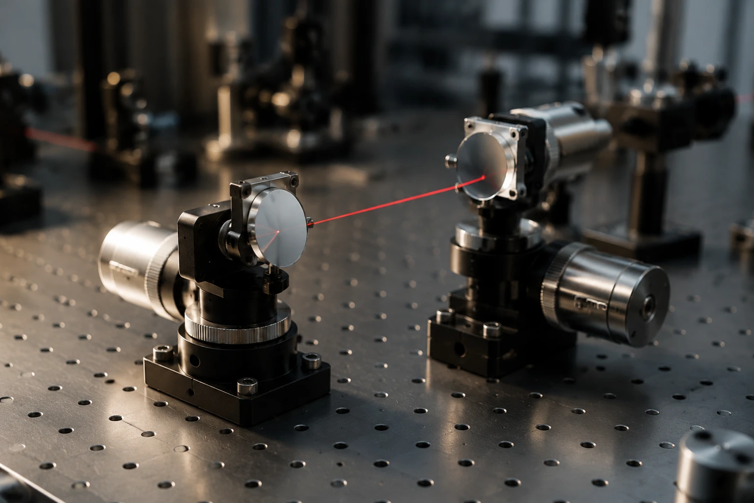
1. Wavelength: What color of light are you looking at? If you are working with visible light or near-IR (like 850nm or 905nm used in many LiDAR systems), you want modules built around Si PIN photodiodes. If you are working in telecom wavelengths (1310nm or 1550nm), you’ll need InGaAs based integrated photodiode modules.
2. Bandwidth vs. Gain:
This is the classic engineering tradeoff. Do you need to see a very fast pulse (high bandwidth), or a very dim light (high gain)? Integrated photodiode modules come in different flavors. Some are optimized for high speed (hundreds of MHz or even GHz) with lower gain. Others have massive internal feedback resistors for high gain but slower speeds. Pick the one that matches the clock speed of your AI sampling rate.
3. Packaging:
Do you need a through-hole TO-can package that you can stick a lens on? Or do you need a tiny surface-mount (SMD) package to cram into a smartwatch? BeePhoton offers various form factors to fit the mechanical constraints of your housing.
Common Mistakes I See Engineers Make
Even with integrated photodiode modules, things can go wrong if you aren’t careful. Here are a few traps I see people fall into:
- Terrible Power Supplies: The TIA inside the module needs power. If your VCC line is noisy because you powered it directly from a cheap switching regulator without any filtering, that noise will couple right into your output signal. Always use a low-dropout (LDO) linear regulator to power your integrated photodiode modules, and put a proper bypass capacitor right at the power pin.
- Impedance Mismatch: If your module outputs a high-speed signal, you need to treat the PCB trace going to the ADC as a transmission line. If the module expects a 50-ohm load and you just run a random trace into a high-impedance ADC pin, you will get nasty reflections.
- Ignoring Ambient Light: Integrated photodiode modules are sensitive. If your system operates outdoors, the sun will saturate the sensor. You definately need to use optical bandpass filters in front of the module to block everything except the specific laser or LED wavelength you care about.
Taking the Next Step in Hardware Design
The hardware landscape is shifting rapidly. With the rise of complex AI processing at the edge, the analog front end can no longer be an afterthought. It is the bottleneck.
If you spend weeks training a neural network but refuse to spend a little extra on high-quality optical components, you are shooting yourself in the foot. I’ve watched too many brilliant software teams get bogged down because their hardware counterparts tried to save pennies on discrete sensors.
Integrated photodiode modules are the ultimate shortcut. They solve the hardest parts of analog routing—the ultra-low current, the parasitic capacitance, the EMI susceptibility—and hand you a clean signal ready for digitization.
If you are currently struggling with a noisy optical design, or if you are architecting a new AI-driven optical system from scratch, do yourself a massive favor. Stop routing bare diodes. Look into the integrated solutions available. Your timeline, your sanity, and your final product’s performance will all vastly improve.
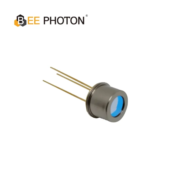
Si PIN Photodiode with low dark current (350-1060nm) PDCT07-001
Achieve high-precision results with our wide spectral range Si PIN photodiode, ideal for spectrometry and analytical instruments. Its ultra-low dark current and high linearity ensure accurate light detection. This photodiode offers a wide spectral response for diverse applications.
FAQ: Everything Else You Need to Know
1. Can integrated photodiode modules handle high-speed LiDAR applications?
Absolutely. Many integrated photodiode modules are specifically designed for ToF (Time of Flight) and LiDAR systems. By keeping the capacitance incredibly low, these modules can achieve bandwidths in the hundreds of megahertz, allowing them to detect the fast nanosecond light pulses required for accurate distance measurement in autonomous vehicles.
2. How do I interface these modules with a microcontroller or ADC?
It’s surprisingly straightforward. The output of integrated photodiode modules is typically a buffered analog voltage. You just route this output pin directly to the analog input pin of your ADC. Just make sure the output voltage swing of the module matches the input range of your ADC (e.g., 0 to 3.3V). For very high speeds, ensure your PCB trace is impedance matched.
3. Are Si PIN based modules better than APD modules?
“Better” depends on the application. Si PIN photodiodes are highly linear, much cheaper, and operate at low voltages (like 5V or 12V). They are perfect for most AI vision, medical, and industrial sorting tasks. APDs (Avalanche Photodiodes) provide internal multiplication, making them better for single-photon counting or extreme long-range LiDAR, but they require dangerous high bias voltages (100V+) and are highly sensitive to temperature changes. For the vast majority of commercial AI edge devices, Si PIN integrated photodiode modules are the smarter, more stable choice.
Ready to Fix Your Optical Signal Path?
If you are tired of debugging noisy analog front ends and want to fast-track your AI hardware development, we have the hardware you need. Getting the right sensor shouldn’t be the hardest part of your project.
At BeePhoton, we design precision optical components built for real-world engineering challenges. Whether you need standard Si PIN detectors or fully optimized integrated photodiode modules, we can help you cut your development time in half and get crystal clear data into your AI models.
Stop fighting parasitic capacitance on your PCB. Let’s talk about your specific application and find the exact module to solve your bottleneck.
Check out our full product lineup at BeePhoton or reach out to us directly through our contact page. You can also shoot an email straight to info@photo-detector.com and one of our engineers will help you spec the perfect part.
Would you like me to help you draft an email to your engineering team summarizing why switching to integrated modules will save your current project’s timeline?