If you’re a hardware engineer trying to pull usable signals out of tiny photocurrents at high speeds, you already know how painful a bad transimpedance amplifier for photodiodes can be. One wrong choice and you’re chasing oscillations at 3 a.m. or drowning in noise that kills your SNR.
I’ve designed more transimpedance amplifier for photodiodes circuits than I care to count — from 10 Mbps fiber receivers to multi-gigahertz LIDAR front-ends. This isn’t another sterile app note. It’s the stuff I wish someone had told me years ago.
Why Most TIA Designs Fail Before They Even Start
Photodiodes spit out current — usually in the nanoamp to microamp range. Your job is to turn that current into voltage without destroying bandwidth or adding ridiculous noise.
A simple resistor does the job in theory. In practice? The photodiode’s junction capacitance (often 10–50 pF) teams up with the resistor to create a pole that kills your speed. That’s exactly why we use a transimpedance amplifier for photodiodes built around an op-amp with feedback.
The magic equation is dead simple:
Vout = –Iphoto × Rf
Where Rf is your feedback resistor. Want 1 V per microamp? Make Rf 1 MΩ. Easy.
The hard part is everything else.
Core Specifications You Must Get Right
Before you open KiCad, write down these four numbers:
| Parameter | What It Means | Typical Target (High-Speed) |
|---|---|---|
| Transimpedance Gain | Vout per input current | 10kΩ – 1MΩ |
| Bandwidth | Usable frequency range | 100 MHz – 2 GHz |
| Input-Referred Noise | Current noise seen at photodiode | < 5 pA/√Hz |
| Stability Margin | How much phase margin you actually have | > 45° |
I’ve seen engineers chase 500 MHz bandwidth while using a 10 pF photodiode and wondering why their circuit rings like a bell. The numbers have to match.
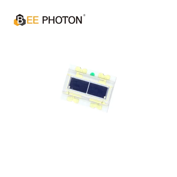
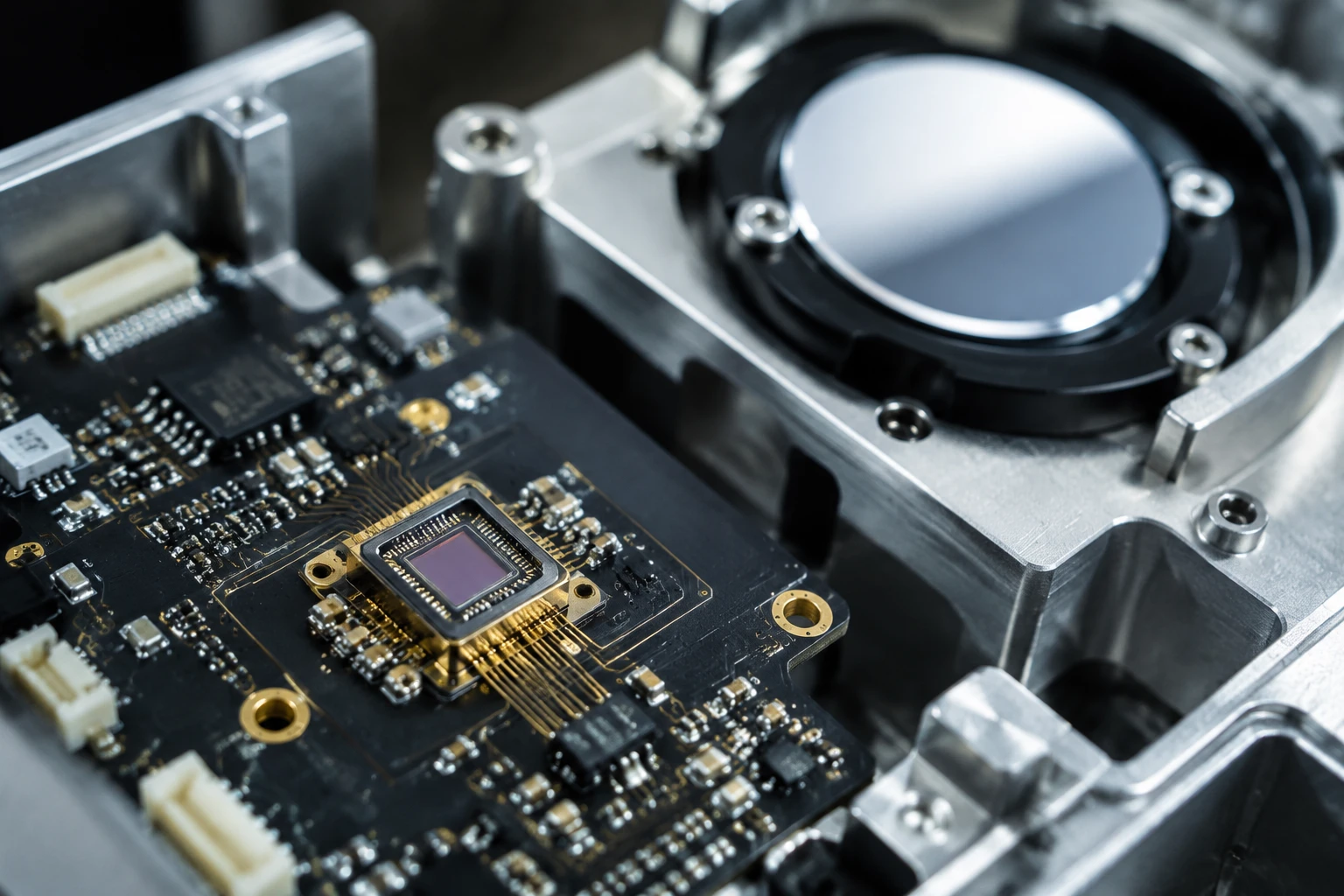
Si PIN Photodiode Array PDCA02-602
The Bee Photon PDCA Series is engineered specifically as a Background Suppression Photodiode to solve complex detection challenges in industrial environments. By utilizing a high-precision two-segment architecture (PD A and PD B), this device allows for differential signal processing, effectively filtering out background interference. It is the premier choice for manufacturers designing reliable background suppression optical switches and proximity sensors.
Step-by-Step: How I Actually Design a Transimpedance Amplifier for Photodiodes
1. Pick the Right Op-Amp (This Is 70% of Success)
Forget general-purpose op-amps. You need:
- High gain-bandwidth product (GBW)
- Low input current noise (not just voltage noise)
- Fast slew rate
- Preferably FET-input
Some parts I’ve had good luck with: OPA657, ADA4817, LTC6268, and the newer LMH2124. The LTC6268 is stupidly good for lower frequencies (<300 MHz) because its current noise is ridiculously low.
2. Calculate Feedback Resistor and Compensation Capacitor
Here’s the practical formula I use instead of the scary textbooks:
Cf ≈ √( (Cin × 4pF) / (2π × Rf × GBW) )
Where Cin is total input capacitance (photodiode + op-amp + stray).
Or if you want it even simpler — start with 0.5 pF and tweak on the bench. I usually end up between 0.3 pF and 2.2 pF in real designs.
3. Deal With the Photodiode Capacitance
This is where a lot of guys get stuck. Si PIN photodiodes from our Si PIN photodiodes category typically run 1.5–12 pF depending on active area and bias voltage.
Bigger area = more capacitance = harder to get high bandwidth. Sometimes it’s worth using a smaller photodiode and adding an optical concentrator. Controversial opinion: many engineers oversize their photodiodes “just to be safe” and end up with a slower, noisier transimpedance amplifier for photodiodes.
4. Layout — This Is Where Magic Happens or Dies
Rules I live by:
- Feedback resistor and capacitor must be as close as physically possible to the op-amp inverting input
- No ground plane under the photodiode or inverting input (reduces capacitance)
- Guard ring around the inverting input tied to ground
- Power supply decoupling within 5 mm of the op-amp
I once fixed a 400 MHz design that was oscillating at 800 MHz just by rotating one capacitor 90 degrees. Layout matters more than most schematics admit.
Noise — The Silent Killer of TIA Performance
The three noise sources you actually need to worry about:
- Feedback resistor thermal noise — √(4kT/Rf)
- Op-amp current noise — especially important at high frequencies
- Op-amp voltage noise multiplied by (Cin/Cf)
I built a spreadsheet that calculates total integrated noise. In one medical imaging project, reducing the voltage noise contribution by picking a better op-amp dropped our noise floor by 9 dB. That was the difference between a product that worked and one that got cancelled.
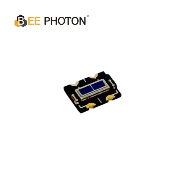
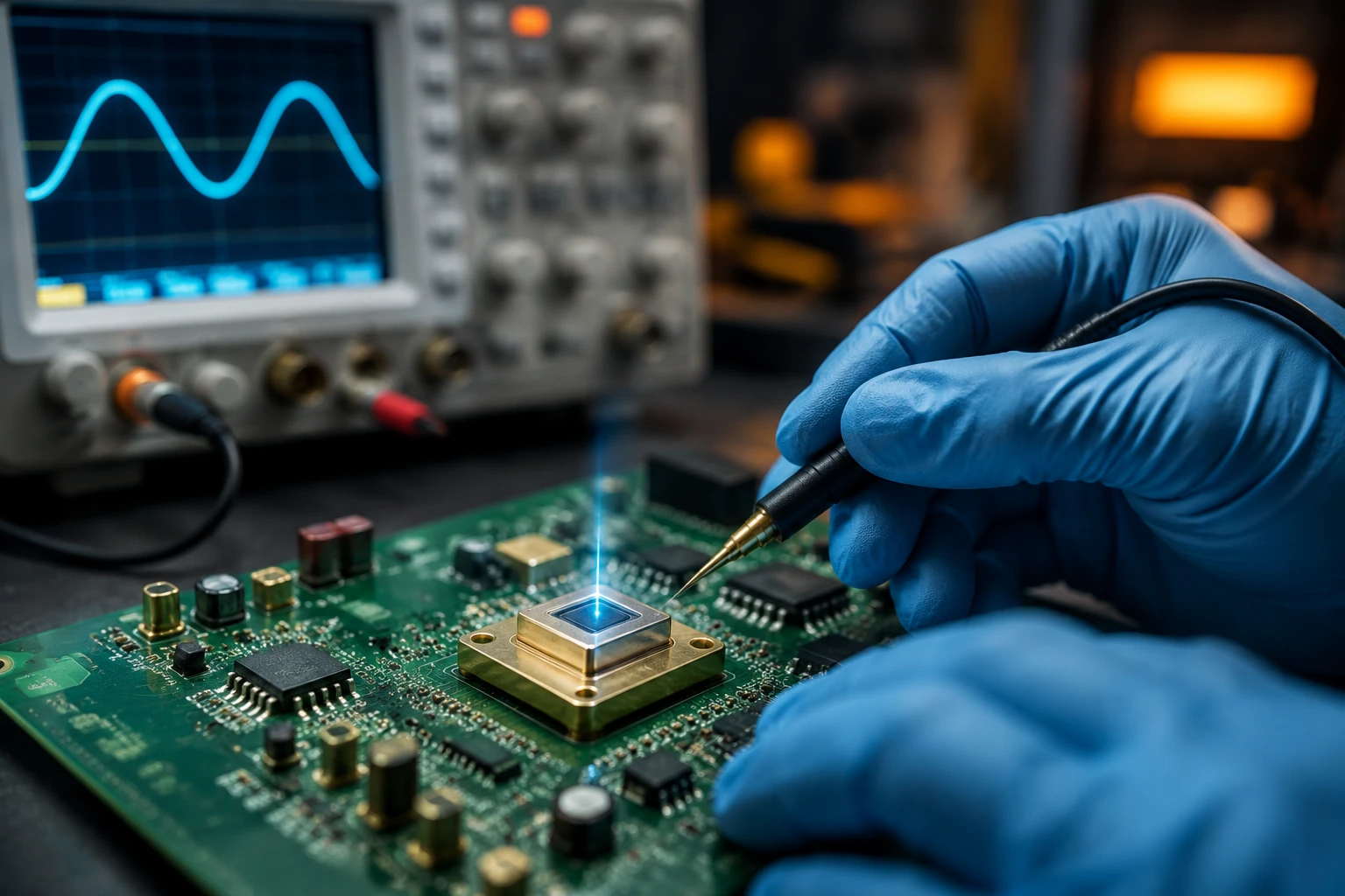
Si PIN Photodiode Array PDCA02-601
The Bee Photon PDCA Series is a precision-engineered Dual PIN Photodiode designed for high-end industrial sensing. Unlike standard single-element detectors, this silicon-based device features a segmented array structure (PD A and PD B), making it the perfect solution for differential sensing and background suppression optical switches. With a wide spectral response from 350nm to 1060nm, it ensures versatile performance across visible and near-infrared wavelengths.
Real Case Studies (No Fluff)
Case 1: Industrial LIDAR Company
Client needed 600 MHz bandwidth with <8 pA/√Hz noise using a 0.3 mm² photodiode. We used the ADA4817-1 with 499 kΩ feedback and 0.5 pF compensation. The first prototype hit 680 MHz. They went from “this is impossible” to “when can we get 1000 pieces?”
Case 2: Quantum Optics Lab
Extremely low light levels. We used a 10 MΩ feedback resistor with the LTC6268 and careful bootstrapping of the photodiode bias. Dark current noise dominated until we added active cooling. The researcher later told me it was the first time they could see single-photon-level statistics without avalanche photodiodes.
Both projects started with the client trying to copy an app note and failing.
Advanced Tricks I Wish I Knew Earlier
- Bootstrapping the photodiode bias to reduce capacitance (huge win)
- Using a TIA with inductive feedback for certain bandwidth shapes
- Adding a post-amplifier instead of cranking Rf too high
- Implementing automatic gain control in the feedback path for dynamic range
Common Mistakes That Waste Months
- Using ceramic capacitors with high voltage coefficient in the feedback path (they become nonlinear)
- Ignoring parasitic inductance in the feedback loop
- Testing with a function generator instead of a real photodiode (completely different impedance)
- Forgetting that photodiode capacitance changes with reverse bias voltage
Ready to Build Your Own Transimpedance Amplifier for Photodiodes?
You don’t have to figure all this out alone.
Whether you need a custom TIA circuit design, help selecting the right Si PIN photodiodes, or just want a second pair of eyes on your schematic, we’ve been there.
Head over to our contact page and tell us what you’re trying to achieve. Or shoot us an email at info@photo-detector.com. Half the time we end up jumping on a quick call and saving people weeks of headache.
Don’t spend another month fighting oscillations that shouldn’t exist in the first place.
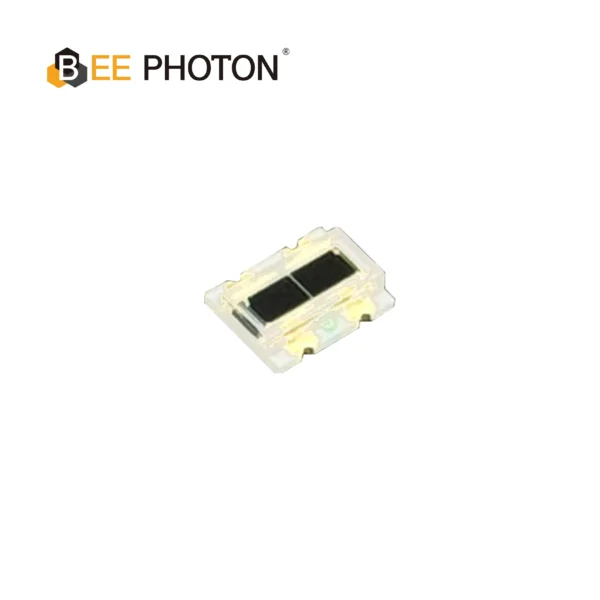
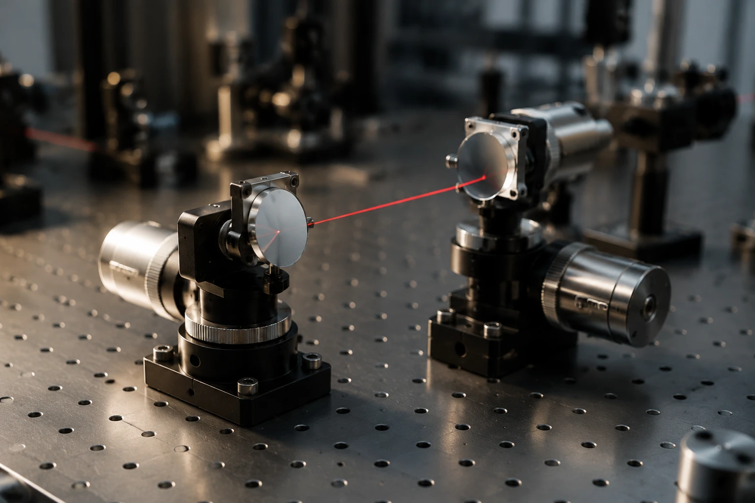
Si PIN Photodiode Array PDCA02-102
The PDCA02-102 is a high-performance Si PIN Photodiode Array designed for precision optical measurement and alignment systems. Engineered by Bee Photon, this 2-segment photodiode delivers a wide spectral response range from 400nm to 1100nm, covering the entire visible light spectrum into the near-infrared (NIR) region.
With its compact COB (Chip on Board) package and resin window, the PDCA02-102 ensures durability and easy integration into compact optical modules. It is specifically optimized for industrial applications where high sensitivity and fast response times are critical.
FAQ
Q1: How do I choose between a FET-input and bipolar op-amp for my transimpedance amplifier for photodiodes?
FET-input (like the OPA657 or LTC6268) almost always wins for photodiodes because their current noise is much lower. Bipolar op-amps only make sense in very specific low-source-impedance cases, which photodiodes aren’t.
Q2: Can I use a transimpedance amplifier IC instead of designing with discrete op-amps?
You can, and sometimes you should. Chips like the MAX40660 or Analog Devices’ integrated TIAs save design time but usually cost more and give you less flexibility. For high-volume or very specific performance, discrete is still king.
Q3: What’s the highest bandwidth I can realistically get with a standard Si PIN photodiode and transimpedance amplifier for photodiodes?
With careful design, good layout, and the right op-amp, 1.5–2 GHz is achievable using smaller photodiodes (<0.5 mm²). Above that you usually need special avalanche photodiodes or different detector technology entirely.
Q4: How critical is the feedback capacitor value really?
Extremely. I usually sweep it in simulation, then put a 1 pF trimmer on the first prototype. Once I find the sweet spot, I replace it with a fixed capacitor. Skipping this step is how you end up with peaking or oscillation.