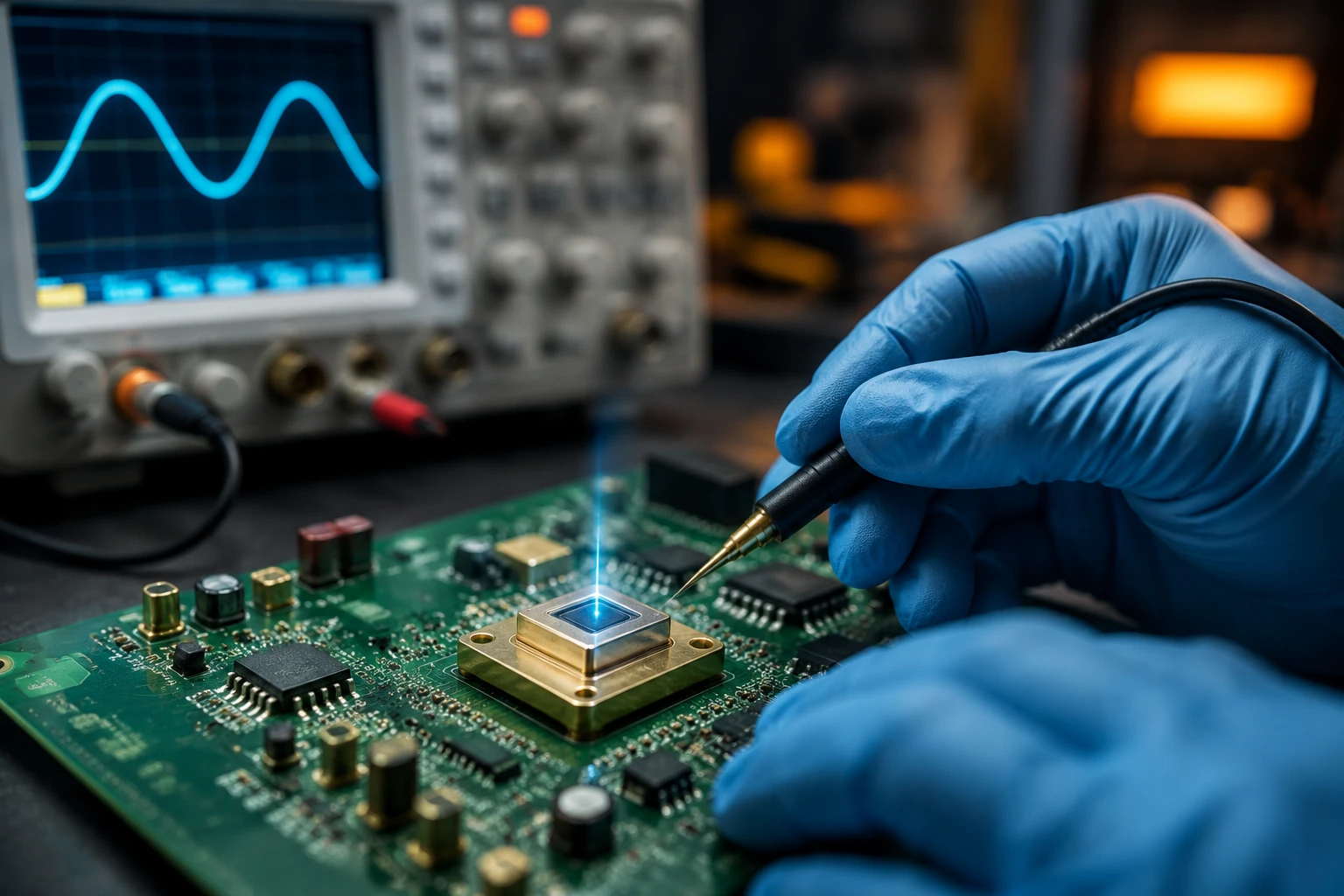
If you’ve ever stared at your oscilloscope wondering why your signal looks so damn noisy even though the light level seems decent, you’re not alone. Most analog circuit engineers I talk to eventually hit the same wall: photodiode noise is eating their SNR for breakfast.
After years of helping customers optimize detection circuits here at BeePhoton, I’ve learned one thing above all—understanding the difference between shot noise and thermal noise isn’t just academic. It’s the difference between a design that works in the lab and one that actually performs in the field.
Today I’m going to walk you through exactly how these two dominant photodiode noise types behave, when each one takes over, and what you can actually do about it. No fluff, no perfect textbook answers—just the stuff we’ve learned the hard way.
Why Photodiode Noise Matters More Than You Think
Let’s be honest. You didn’t come here for theory. You’re probably trying to squeeze a few more dB of SNR out of a lidar receiver, a medical sensor, or some industrial optical measurement system.
Every nanoamp of photodiode noise current directly limits your minimum detectable signal. And here’s the part many engineers miss: the dominant photodiode noise source changes depending on your operating conditions. What works at high light levels falls apart at low light levels, and vice versa.
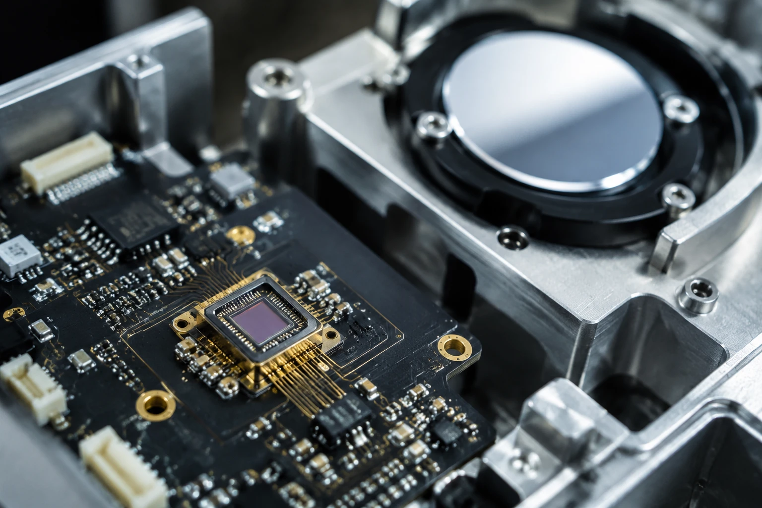
Our Si PIN photodiodes regularly get used in applications where customers are chasing sub-picoamp noise floors. Getting there means you have to know your enemy.
The Main Types of Photodiode Noise
There are four noise sources you’ll usually wrestle with in a photodiode circuit:
- Shot noise (signal-dependent and dark-current-dependent)
- Thermal noise (from the load resistor and amplifier)
- 1/f noise (mostly annoying at very low frequencies)
- Generation-recombination noise (usually smaller in good silicon PINs)
For most broadband applications above a few kHz, the battle comes down to shot noise versus thermal noise. So let’s dig into both.
What Is Shot Noise in Photodiodes?
Shot noise comes from the discrete nature of electrons. Light arrives as photons, electrons get generated randomly, and that randomness creates noise.
The formula for the RMS shot noise current is:
i_shot = sqrt(2 * q * (I_photo + I_dark) * BW)
Where:
q= 1.6 × 10^-19 coulombs (electron charge)I_photo= photocurrent in amperesI_dark= dark current in amperesBW= noise bandwidth in Hz
Notice something important: shot noise increases with the square root of your signal current. This is why photodiode noise gets worse as your signal gets stronger—until eventually shot noise dominates everything.
I remember one customer who kept increasing LED power thinking it would improve their SNR. They actually made it worse after a certain point because they pushed the system into shot-noise-limited territory while their amplifier was still contributing tons of thermal noise. Classic mistake.
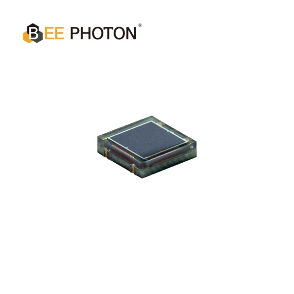
Si PIN Photodiode with NIR sensitivity enchanced (350-1100nm) PDCC34-501
Bee Photon offers a High Stability PIN Photodiode for precise industrial sensing. This NIR enhanced photodiode ensures reliable measurements from 350-1100nm. A top choice for a high stability photodiode.
When Shot Noise Wins
Shot noise usually becomes the dominant photodiode noise source when:
- Light levels are high (photocurrent > ~0.1–1 µA depending on your setup)
- You’re using a low resistance transimpedance amplifier
- Your bandwidth is high
In our testing with silicon PIN photodiodes, once photocurrent exceeds about 500 nA in a 1 MHz bandwidth circuit, shot noise typically overtakes thermal noise from a 10 kΩ feedback resistor.
Thermal Noise (Johnson Noise) in Photodiode Circuits
Thermal noise comes from the random thermal motion of electrons in resistors. It’s always there, even in complete darkness.
The RMS thermal noise current is:
i_thermal = sqrt(4 * k * T * BW / R_f)
Where:
k= 1.38 × 10^-23 J/K (Boltzmann’s constant)T= temperature in KelvinR_f= feedback resistance (or load resistance)BW= bandwidth in Hz
Notice that thermal noise goes down as you increase the resistance. This is why high transimpedance gains help so much at low light levels.
Here’s something most application notes won’t tell you: cooling the circuit helps way more than people expect. Every 25°C drop in temperature gives you about 0.5 dB improvement in thermal photodiode noise. We’ve seen customers get almost 2 dB total SNR improvement just by adding a TEC to the photodiode and first-stage amplifier.
Shot Noise vs Thermal Noise: Head-to-Head Comparison
Let me give you some real numbers. I ran these calculations for a typical BeePhoton Si PIN photodiode at 25°C with 1 MHz bandwidth:
| Condition | Photocurrent | Feedback R | Shot Noise (pA rms) | Thermal Noise (pA rms) | Dominant Noise | Total Noise (pA rms) |
|---|---|---|---|---|---|---|
| Low light | 10 nA | 1 MΩ | 2.5 | 4.1 | Thermal | 4.8 |
| Medium light | 100 nA | 100 kΩ | 5.7 | 12.9 | Thermal | 14.1 |
| High light | 1 µA | 10 kΩ | 18.0 | 40.8 | Thermal | 44.7 |
| Very high light | 10 µA | 1 kΩ | 56.6 | 129 | Shot | 141 |
| Optimized low light | 10 nA | 10 MΩ | 2.5 | 1.3 | Shot | 2.8 |
Look at that last row. By increasing the feedback resistor to 10 MΩ, thermal noise dropped dramatically and shot noise became dominant. Total photodiode noise improved by almost 5× compared to the non-optimized high light case.
This table gets shown to almost every customer who contacts us about SNR problems. The transition point between thermal and shot noise limited performance is usually the most important thing to find.
How to Calculate Total Photodiode Noise
The total noise current isn’t just shot plus thermal. Because they’re uncorrelated, you add them in quadrature:
i_total = sqrt(i_shot² + i_thermal² + i_amp² + ...)
I can’t tell you how many times I’ve seen engineers add the numbers linearly. Don’t do that. It overestimates the total photodiode noise by quite a bit when one source dominates.
We built a simple Excel calculator for customers that includes dark current, photocurrent, temperature, bandwidth, and op-amp voltage/current noise. Want one? Just reach out.
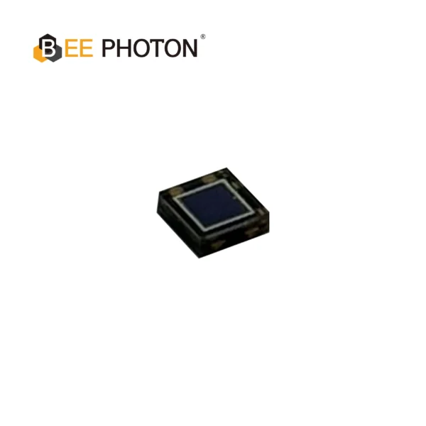
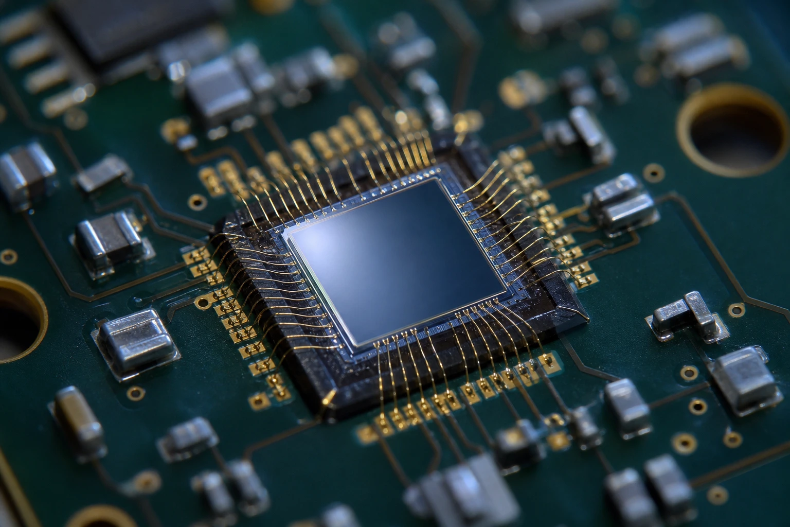
Si PIN Photodiode with low dark current (350-1060nm) PDCC07-003
Enhance your industrial automation systems with our low dark current Si PIN photodiode. This industrial automation photodiode (350-1060nm) offers superior precision and reliability.
Practical Tips for Beating Photodiode Noise
Here’s what actually works in real designs:
1. Choose the Right Photodiode
Not all silicon PINs are created equal when it comes to photodiode noise. Lower dark current devices give you more headroom before shot noise takes over. Our Si PIN photodiodes are specifically sorted for low dark current in many cases.
2. Optimize Transimpedance at the Right Point
Find where shot noise and thermal noise cross over in your circuit. That’s your sweet spot. Going higher in gain after that point mainly reduces bandwidth without helping SNR much.
3. Consider Cooling
If you’re chasing ultimate performance, cooling the detector can help both shot noise (through reduced dark current) and thermal noise.
4. Watch Your Op-Amp
Some engineers spend weeks optimizing the photodiode only to get killed by amplifier voltage noise. The ADA4898 and OPA140 series have been our go-to parts lately.
5. Bandwidth Limiting
If your application allows it, reduce your bandwidth. Photodiode noise scales with square root of bandwidth. Cutting bandwidth by 4× gives you 6 dB better SNR.
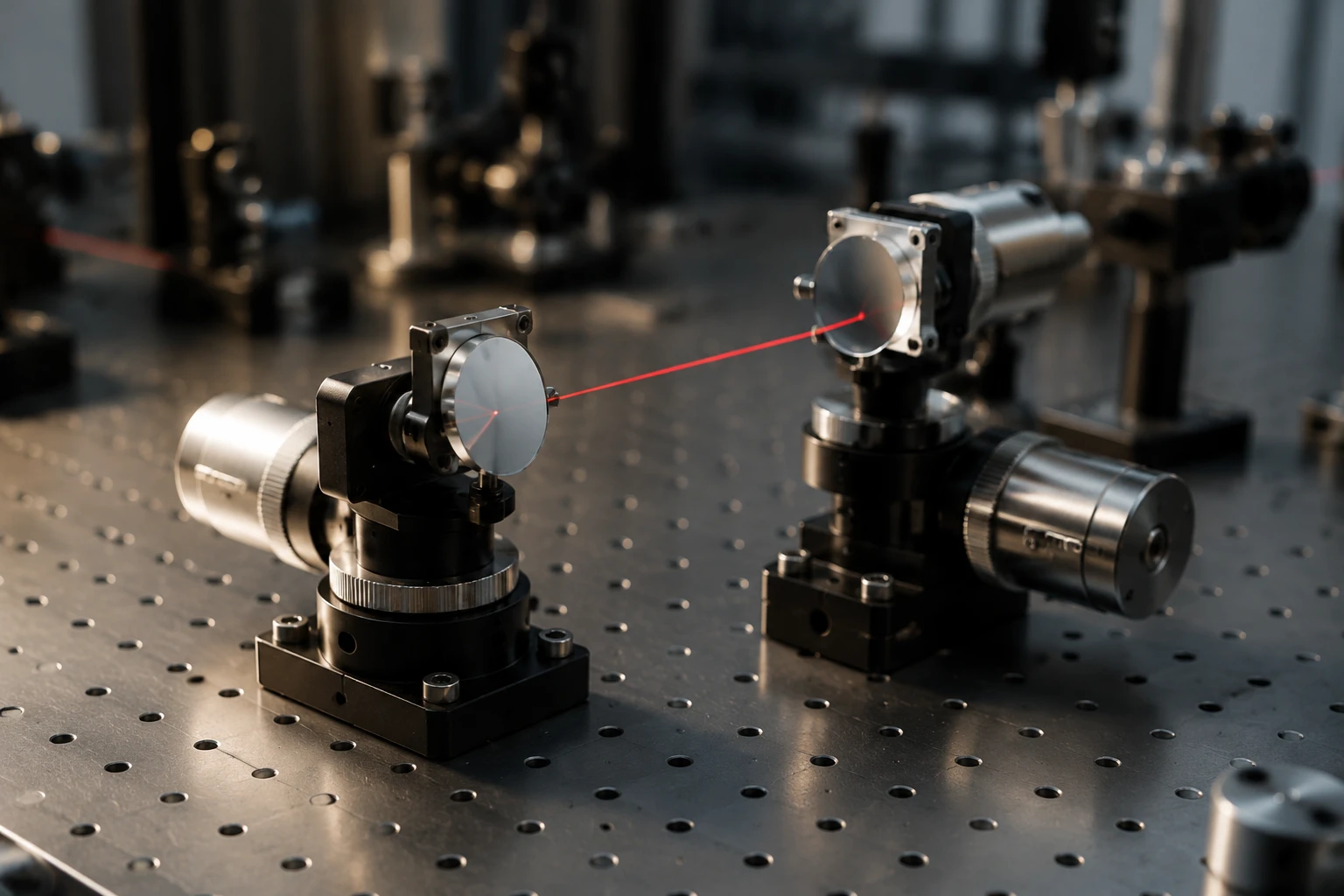
Real Application: Lidar Receiver That Actually Worked
One customer came to us with a lidar system that was only achieving about 35 dB SNR at their target range. After looking at their circuit, we saw they were heavily thermal noise limited because they used a relatively low 50 kΩ transimpedance with a photodiode that had decent dark current.
We switched them to one of our lower dark current Si PIN photodiodes, increased transimpedance to 1 MΩ, and added some careful filtering. The photodiode noise dropped enough that they gained 9 dB of SNR. That was the difference between a product that barely worked and one that exceeded their specifications.
I can’t name the customer, but I can tell you they went from being ready to scrap the design to shipping units within two months.
Choosing the Right Si PIN Photodiode for Low Noise Applications
Not every application needs the absolute lowest photodiode noise. Sometimes cost and bandwidth matter more. The key is matching the detector to your actual operating conditions.
When customers contact us, we usually ask four questions:
- What’s your expected photocurrent range?
- What bandwidth do you actually need?
- What’s your maximum acceptable dark current?
- Are you willing to cool the detector?
The answers to these questions almost always point us to the right device from our Si PIN photodiode lineup.
Wrapping Up: Know Your Noise
Here’s the real takeaway: stop treating photodiode noise as one generic thing. Shot noise and thermal noise behave completely differently and respond to different fixes.
The engineers who get the best performance aren’t necessarily the smartest—they’re usually the ones who measured their actual noise contributions and optimized the right parameter.
If you’re struggling with SNR right now, take a step back and figure out whether shot noise or thermal noise is running the show in your circuit. The answer changes everything.
Need help figuring it out? Our team actually enjoys this stuff. Drop us a message on the contact page or email info@photo-detector.com. We’re happy to look at your circuit and give practical feedback—sometimes even a quick calculation that saves you weeks of trial and error.
Si PIN Photodiode Array PDCA02-601
The Bee Photon PDCA Series is a precision-engineered Dual PIN Photodiode designed for high-end industrial sensing. Unlike standard single-element detectors, this silicon-based device features a segmented array structure (PD A and PD B), making it the perfect solution for differential sensing and background suppression optical switches. With a wide spectral response from 350nm to 1060nm, it ensures versatile performance across visible and near-infrared wavelengths.
FAQ
What is the main difference between shot noise and thermal noise in photodiodes?
Shot noise comes from the random arrival of photons and generation of electrons—it increases with signal strength. Thermal noise comes from the random motion of electrons in resistors and decreases as you increase feedback resistance. Most circuits are thermal noise limited at low light levels and become shot noise limited at higher light levels.
How can I tell which type of photodiode noise is limiting my SNR?
Measure the noise with the light source on and off. If the noise increases significantly with light, you’re probably in the shot noise region. If the noise stays roughly the same, thermal noise or amplifier noise is likely dominant. The table in this article gives you real calculated crossover points.
Does cooling the photodiode actually reduce photodiode noise significantly?
Yes. Every 25°C reduction cuts dark current (and therefore shot noise from dark current) by roughly half for silicon devices. Thermal noise also drops because of the direct temperature dependence. We’ve seen total noise improvements of 40-50% in some cooled designs.
Should I always use the highest possible transimpedance gain?
No. There’s a point where increasing gain further doesn’t help because you’ve already made thermal noise negligible and shot noise is now dominant. Plus you lose bandwidth. The optimal gain is usually where shot noise and thermal noise are roughly equal.