If you have ever stood beside a modern logistics cross-belt sorter or a pharmaceutical blister-pack line running flat out at 5 to 7 meters per second, you know that distinct mechanical roar. It is a rhythmic hum punctuated by rapid air blasts and mechanical diverters firing hundreds of times every minute. In that environment, missed parts mean pile-ups, crushed goods, and plant managers furiously radioing the maintenance shack.
When sorting small items—like plastic ampoules, miniature electronics, or polybagged hardware with millimeter gaps between them—the optical sensing subsystem faces an unforgiving timing budget. If your conveyor moves at 6 m/s, an object with an edge gap of 1 mm crosses your light path in just 166 microseconds. But because industrial plants are flooded with optical interference, you cannot just shine a simple flashlight beam across the belt. You have to modulate your light source at 200 kHz, 500 kHz, or even 2 MHz.
At those frequencies, your everyday phototransistors and cheap detectors fall flat on their faces. You do not just need general light detection; you need sub-0.15 µs (150 nanosecond) rise and fall transitions. Simply put: you need a dedicated Fast Response PIN Diode.
At BeePhoton, we often talk with hardware designers who spent weeks pulling their hair out over false triggers and erratic edge counts, only to discover their detector was choking on its own internal capacitance. Let us walk through the real physics, practical conveyor design calculations, packaging traps, and how to pick the right silicon to keep your sorting line running at full clip.
The Real Problem: Why High-Speed Conveyors Choke Standard Sensors
Most basic optical gates on packaging machinery rely on simple retroreflective or through-beam setups. On a slow bottling line running at 0.5 m/s, you can slap in almost any garden-variety photodetector, hook it to an op-amp, and walk away happy.
Try that on a high-speed parcel sorter, and the system falls apart.
Optical Signal Flow on Modern Sortation Lines:
High-Frequency Pulsed Emitter (850nm / 940nm) → Conveyor Object Passing Through Beam → Fast Response PIN Diode → Transimpedance Amplifier (TIA) → High-Speed Comparator → Motion Controller / Ejection Diverter
When parcels move fast, your spatial accuracy is handcuffed to your sensor’s temporal response. If your photodetector takes 1.5 microseconds to pull its output low when the beam is broken, an envelope moving at 6 m/s has already traveled 9 millimeters down the belt before your PLC or micro even knows it arrived. That spatial drift creates massive positioning jitter, causing diverter paddles to jam boxes or misfire completely.
To make things harder, modern distribution centers are flooded with optical garbage: high-frequency PWM warehouse LED lighting, laser barcode scanners sweeping overhead, light curtains, and passing forklift strobes. Standard continuous-wave (CW) light sensing gets blinded almost immediately.
That is why you must modulate your emitter. But if you run a 1 MHz carrier frequency, each pulse lasts a mere 500 nanoseconds. If your detector has a rise time of 350 ns, the output signal never climbs to full amplitude. The pulses get squashed, your signal-to-noise ratio goes down the drain, and your comparator logic starts hallucinating phantom parcels. Choosing an optimized fast response PIN diode engineered for sub-150 nanosecond switching is the only reliable way to preserve pulse fidelity.

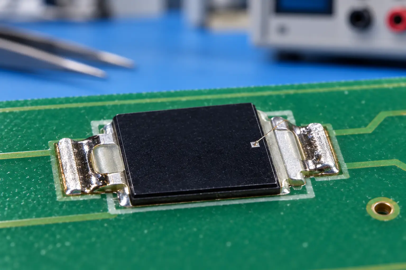
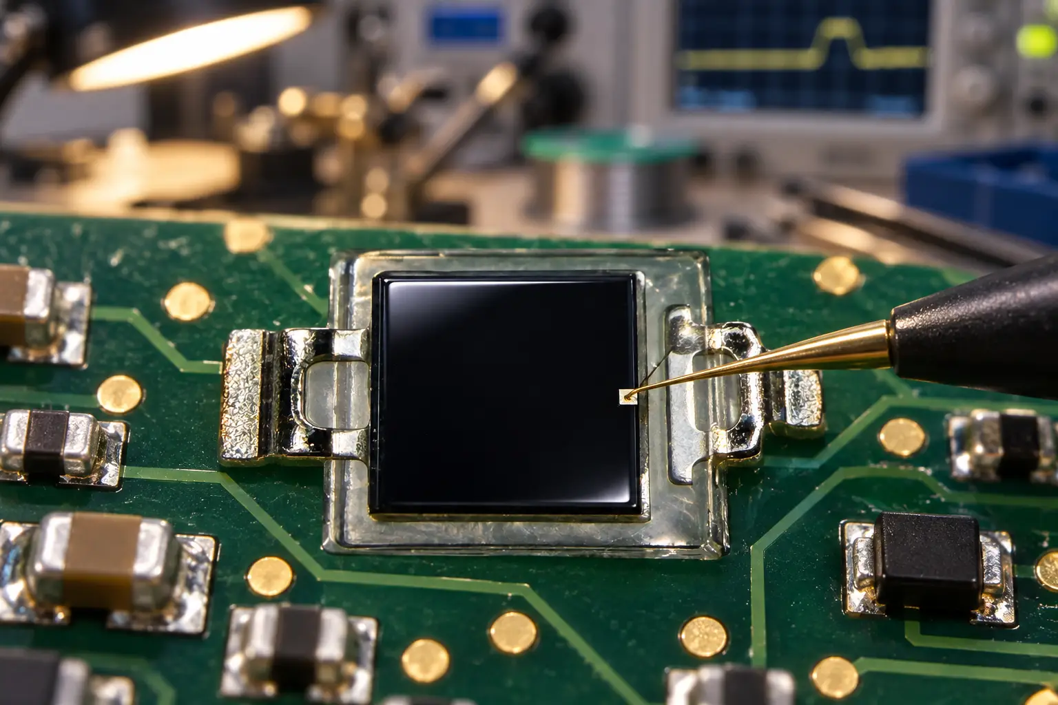
Si PIN photodiode PDCP08 Series PDCP08-511
The PDCP08-511 is a high-performance Black Epoxy PIN Photodiode designed for precision infrared applications. Encased in a special black epoxy resin, this sensor effectively acts as a daylight filter, blocking visible light interference while maximizing sensitivity at 940nm. With a large 2.9×2.9mm active area and low dark current, it ensures reliable signal detection for optical switches and remote control systems, even in noisy ambient light environments.
The Physics of Speed: Transit Time vs. Junction Capacitance
Why does an engineer choose a fast response PIN diode instead of a regular PN photodiode? It comes down to the intrinsic (I) layer sandwiched between the P-doped and N-doped silicon.
A standard PN photodiode features a thin depletion region under zero bias. Photons hitting the silicon outside this narrow zone generate electron-hole pairs that wander around through slow diffusion before reaching the electrical junction. Diffusion is agonizingly sluggish.
A fast response PIN diode inserts a wide, undoped intrinsic silicon layer. When you apply a reverse bias, this entire intrinsic region fully depletes. Photons are absorbed directly inside a massive electric field, meaning photogenerated charge carriers drift immediately at saturation velocity. If you want to review the semiconductor carrier physics in depth, Wikipedia’s PIN diode technical overview provides great background on carrier drift mechanics.
The overall rise time (tr) of your fast response PIN diode is dictated by two competing physical factors:
tr_total = sqrt(tr_transit^2 + tr_RC^2)
Let us look at each part so you know what is actually slowing your circuit down.
1. Carrier Transit Time (tr_transit)
This represents the duration required for carriers to drift across the depleted intrinsic layer width (W):
tr_transit = W / v_sat
In silicon, carrier saturation velocity (v_sat) reaches approximately 10^7 cm/s under high field strength. For a typical intrinsic layer width of 20 µm, your transit time sits right around 0.2 nanoseconds. In practical conveyor sensing systems operating below 50 MHz, transit time is rarely your limiting bottleneck.
2. The Real Killer: Junction Capacitance and RC Time Constant (tr_RC)
The true obstacle on your conveyor sensor board is the junction capacitance (Cj) interacting with your circuit’s load resistance (RL):
tr_RC = 2.2 * RL * (Cj + C_stray)
Junction capacitance itself is dictated by the active silicon area (A), the intrinsic layer width (W), and the dielectric permittivity of silicon (epsilon):
Cj = (epsilon * A) / W
Academic resources and technical publications on IEEE Xplore consistently confirm that reducing Cj requires either widening the depletion region W via reverse biasing, or reducing the active die area A.
Here is where real hardware engineering involves compromises:
- If you pick an oversized active area (say, 10 mm² so plant technicians can align the sensor across a vibrating 2-meter conveyor without squinting), Cj blows up to 50 pF or 100 pF. Even with a modest load resistor, your rise time stretches way past your 0.15 µs target.
- If you shrink the active area too much (down to 0.2 mm²), your optical alignment tolerance becomes razor-thin, and everyday conveyor vibration will knock the sensor out of alignment.
An industrial-grade fast response PIN diode balances this trade-off, giving you an active area large enough for mechanical stability while keeping junction capacitance down between 3 pF and 15 pF under modest reverse bias.
Bandwidth Estimation Shortcut:
Bandwidth (BW) = 0.35 / tr_totalIf your carrier modulation requires a 2.5 MHz clean square wave, you need an analog bandwidth of at least 3.5 MHz to keep pulse shape integrity. Solving for rise time:
tr_max = 0.35 / 3,500,000 Hz = 100 nanoseconds (0.10 µs)
This is why picking a fast response PIN diode with guaranteed sub-0.15 µs switching is essential.
Packaging Traps: Inductance, Stray Capacitance, and Black Epoxy
You can source the fastest silicon die available, but if you wrap it in the wrong physical packaging, you will destroy your microsecond rise time photodiode performance. Packaging rise time tr effects are a notorious trap on factory floors.
Every single millimeter of a through-hole photodiode lead introduces roughly 1.0 to 1.2 nH of parasitic inductance. When that inductance meets your photodiode capacitance and board layout traces, you accidentally construct an RLC resonator right at the input of your preamplifier.
The Parasitic RLC Consequence:
Leaded Component Inductance + Junction Capacitance (Cj) + Board Trace Capacitance → Front-End RLC Resonance.Result: Signal ringing, false comparator tripping, and extended pulse decay tails that mask trailing-edge object transitions.
For high-speed sorting, selecting a surface-mount (SMD) fast response PIN diode is generally superior to leaded radial packages. SMD construction slashes pin inductance to negligible levels, preventing false edge triggers and clean signal recovery.
Visible Light Interference & Black Epoxy Packaging
Ambient illumination is another massive headache. Distribution facilities use blazing high-bay LED lamps. If your detector picks up broad-spectrum light (400 nm to 1100 nm), that ambient glow generates a steady DC baseline photocurrent.
This baseline current drains your amplifier’s headroom, pushes the detector toward saturation, and stretches your pulse rise times. The NIST Optical Radiation Group maintains helpful guidelines regarding background radiation rejection in industrial radiometric sensing.
To fix this without spending money on external optical glass filters, look for a fast response PIN diode cast in daylight-filtering black epoxy. This resin blocks visible light below 700 nm while letting near-infrared emitter light (850 nm to 940 nm) pass right through.
At BeePhoton, our silicon lineup addresses these exact packaging and optical demands:
- PDCP08-511 Black Epoxy PIN Photodiode: Formulated with an integrated daylight-filtering black epoxy package. It blocks overhead visible plant lighting, making this fast response PIN diode the premier choice for open conveyor frames prone to direct sunlight or factory LED wash.
- PDCP08-502 2.9×2.8mm Silicon PIN Photodiode: A compact surface-mount fast response PIN diode engineered with minimal parasitic capacitance and tiny footprint dimensions. It excels in tight optical arrays where multi-beam light curtains must fit into cramped conveyor extrusions.
- PDCP08-501 Silicon PIN Photodiode: A highly versatile silicon detector offering balanced active area, broad spectral sensitivity, and reliable sub-0.15 µs transition speeds when paired with custom external optical filtration.
Photodetector Comparison for Fast Automation Lines
Here is how different detector architectures stack up when integrated into high-speed material handling systems:
| Detector Architecture | Typical Active Area | Typical Capacitance (Cj) | Typical Rise Time (tr) | Ambient Light Rejection | Typical Conveyor Use Case |
|---|---|---|---|---|---|
| Standard Phototransistor | 1.0 – 2.0 mm² | High (Miller multiplication) | 5.0 µs – 15.0 µs | Poor / None | Slow carton lines (< 1.5 m/s); low modulation frequencies (< 15 kHz). |
| Generic Large-Area PN Diode | 10.0 mm² | 70 – 150 pF | 0.8 µs – 2.0 µs | Clear casting | Wide-area perimeter safety gates; unmodulated DC break-beams. |
| BeePhoton PDCP08-511 | Optimized NIR die | Low (fully depleted) | < 0.15 µs | Integrated Black Epoxy | High-speed sorting lines exposed to direct ambient factory lighting; 500 kHz+ pulse modulation. |
| BeePhoton PDCP08-502 | Compact SMD die | Ultra-low (< 10 pF) | < 0.08 µs | Clear SMD window | Space-constrained parcel singulators; high-density multi-beam arrays. |
| BeePhoton PDCP08-501 | Standard Si die | Low | < 0.12 µs | Broad spectral window | Multi-wavelength optical inspection; high-frequency optical sensor heads. |
Looking at this comparison, you can see why legacy phototransistors choke on fast sorting belts. A rise time of 10 microseconds means your sensor is completely blind to short pulse intervals. Deploying an optimized fast response PIN diode provides an immediate jump in temporal resolution.

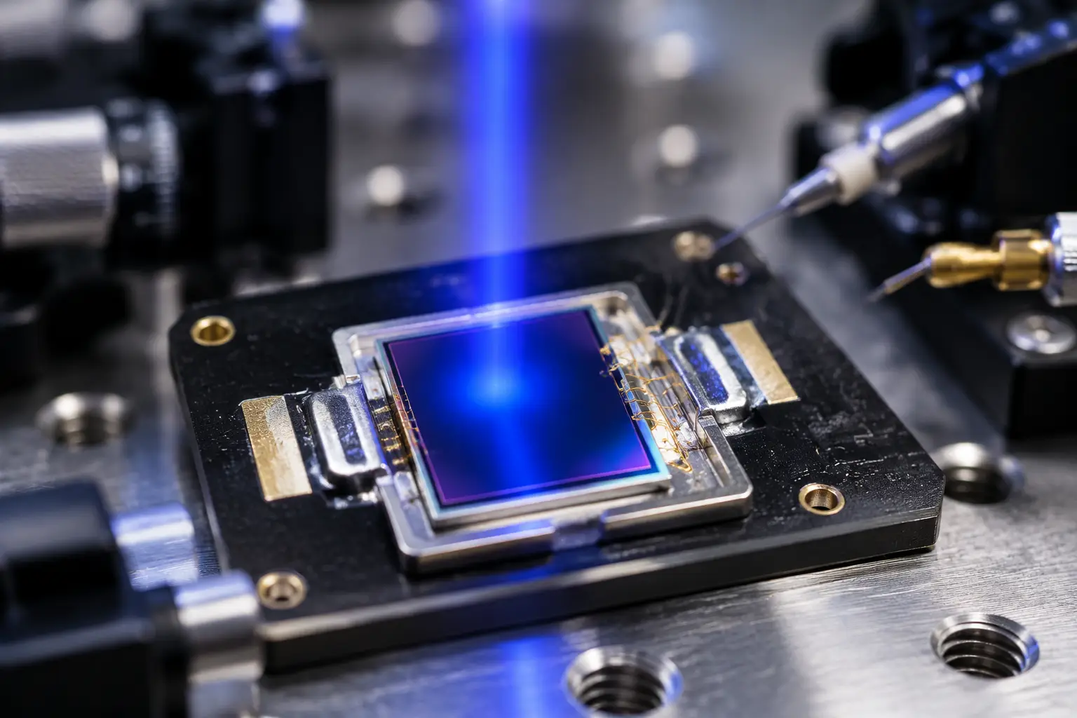
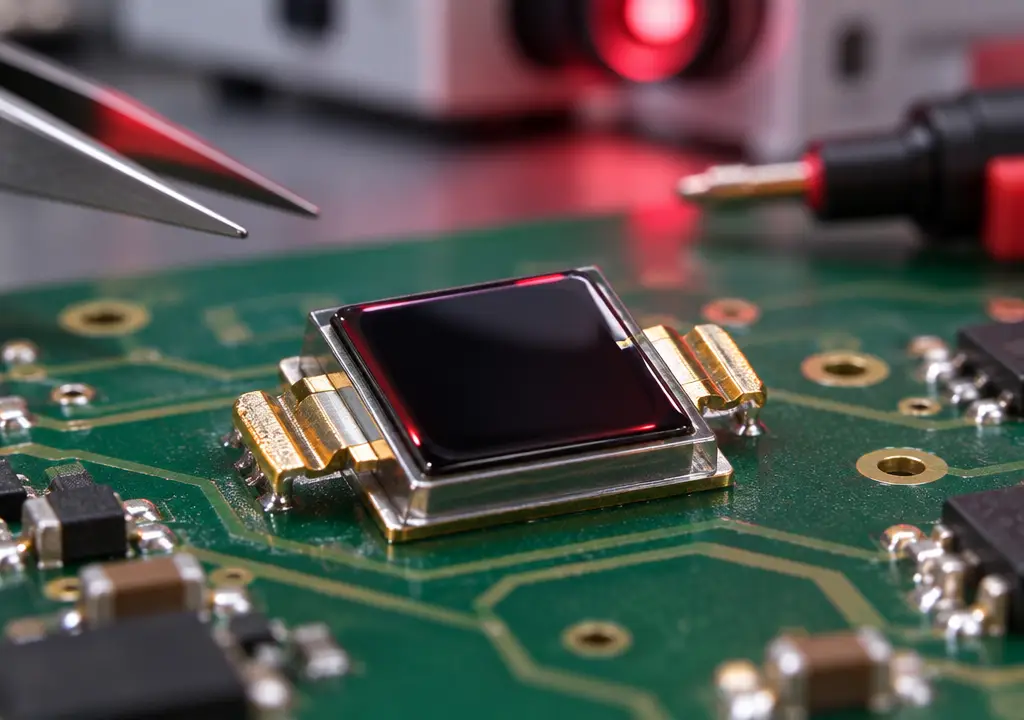
Si PIN photodiode PDCP08 Series PDCP08-502
The PDCP08-502 is a high-response 2.9×2.8mm Silicon PIN Photodiode designed for precision photoelectric applications. Featuring low junction capacitance, low dark current, and a wide spectral range (340-1100nm), it is the ideal component for optical switches and compact sensing modules requiring stable and fast signal output.
Hardware Layout: Squeezing Nanoseconds Out of Your Circuit
Sourcing a top-tier fast response PIN diode is only half the battle; the rest happens on your PCB. Here are four workbench-tested rules to keep your high frequency optical sensor operating at maximum speed:
1. Always Run Photoconductive Mode (Apply Reverse Bias)
Never run a high-speed conveyor sensor in photovoltaic (zero bias) mode. While zero bias yields ultra-low dark current, it leaves your junction capacitance at maximum value.
Bias vs. Capacitance Dynamic:
Applying Reverse Bias Voltage (Vr) → Depletion Layer (W) Expands → Junction Capacitance (Cj) Drops → Rise Time (tr) Drops Dramatically.
Hooking your fast response PIN diode up to a 5V, 10V, or 12V reverse bias reduces its internal capacitance by 60% to 80% compared to unbiased operation. While you introduce a few nanoamps of dark current, your AC-coupled amplifier ignores this DC offset entirely, while your pulse bandwidth jumps dramatically.
2. Avoid the High-Value Load Resistor Trap
If you connect your photodiode directly to a load resistor (RL) driving a comparator, you must calculate your maximum allowable resistance:
RL <= tr_target / (2.2 * (Cj + C_stray + C_in))
Suppose your total capacitance is 15 pF and your rise time budget is 100 ns:
RL <= (100 * 10^-9) / (2.2 * 15 * 10^-12) = 100 * 10^-9 / 3.3 * 10^-11 = 3030 Ohms (~3 kOhm)
If an engineer mistakenly drops in a 100 kOhm resistor to boost signal amplitude without adding an active gain stage, the rise time shoots up:
tr = 2.2 * 100,000 * 15 * 10^-12 = 3.3 microseconds!
That mistake instantly cripples your carrier frequency. Keep your load resistance small, or route your fast response PIN diode directly into a dedicated Transimpedance Amplifier (TIA).
3. Tame Op-Amp Ringing with Feedback Capacitance
When coupling a fast response PIN diode to a transimpedance amplifier, the diode’s junction capacitance sits across the op-amp’s inverting input. This introduces a zero into the feedback network, degrading phase margin and causing severe ringing or oscillation.
To stabilize the circuit, place a small feedback capacitor (Cf) across your feedback resistor (Rf):
Cf = sqrt( C_total / (2 * pi * Rf * GBW) )
Where:
- C_total = Cj + C_trace + C_amp_differential
- GBW is the Gain-Bandwidth Product of your chosen operational amplifier.
Skipping this tiny capacitor turns your clean pulses into oscillating bursts that cause downstream logic to count three or four parcel edges instead of one.
4. Ground Planes and Guard Rings
Never route your sensitive photodiode anode or cathode traces over noisy digital buses or switched-mode power supplies. Keep trace lengths between your fast response PIN diode and the preamplifier input under 10 millimeters.
Surround high-impedance analog nodes with an analog guard ring tied to clean ground. This stops surface board leakage currents from triggering drift, especially in hot, humid, or dusty warehouse environments. When machinery safety is involved, design teams often cross-check optical edge integrity against safety standards like ISO 13849-1 to ensure sensor responsiveness does not drift over operating life.
Case Study: Fixing Diverter Jitter on a 5.8 m/s Parcel Singulator
Let us look at an anonymized, real-world case where switching to an optimized fast response PIN diode solved a persistent field failure on an automated conveyor line.
The Problem
A distribution equipment builder designed a parcel singulator line operating at 5.8 m/s. The system used an array of optical through-beam sensors spaced 15 mm apart to measure the exact length and gap spacing of incoming polybags and flat cardboard mailers. To ignore ambient lighting, the emitter LEDs were modulated at 250 kHz.
The engineering team originally selected a low-cost, through-hole photodiode with an unverified rise time rated around 1.4 µs.
The failure mode was severe: flat polybags and envelopes thinner than 2 mm were routinely miscounted or completely missed. When items moved at 5.8 m/s, the sensor’s sluggish rise and fall transitions caused comparator switching thresholds to wander by up to 14 µs depending on object opacity and preceding light history.
Position Error Calculation:
Position Uncertainty = Conveyor Belt Velocity * Timing Jitter
Position Uncertainty = 5.8 m/s * 14 µs = 81.2 mm (~8.1 cm)
An 8-centimeter positioning error completely wrecked the system. Downstream pneumatic ejection gates fired either too early or too late, damaging packages, jamming diversion gates, and shutting down the sortation wing.
Edge Transition Comparison:
- Legacy Generic Photodiode (tr = 1.4 µs): Sluggish, rounded waveforms → Severe comparator threshold drift → Up to 81 mm spatial positioning error.
- Fast Response PIN Diode (tr < 0.15 µs): Sharp, defined square waves → Rock-solid threshold crossing → Under 0.5 mm spatial positioning error.
The Fix
The integrator re-engineered the optical receiver board with three concrete upgrades:
- Replaced the sluggish detector with a BeePhoton PDCP08-511 Black Epoxy PIN Photodiode. The integrated black epoxy filtered out ambient DC light from overhead warehouse fixtures.
- Applied a regulated 10V reverse bias to the fast response PIN diode, fully depleting the intrinsic region and dropping Cj to minimal levels.
- Optimized the front-end TIA feedback loop with a precise feedback capacitor (Cf), establishing a clean system rise time under 115 nanoseconds.
The Results
- Receiver bandwidth expanded smoothly past 3.0 MHz, reproducing the 250 kHz square wave pulses without edge distortion.
- Overall timing jitter collapsed from 14 µs down to under 75 nanoseconds.
- Spatial positioning uncertainty dropped from 81.2 mm down to less than 0.45 mm at full belt speed.
- Package sortation accuracy rose to 99.99%, completely eliminating diverter gate jams.
This case underlines why treating optical detectors as generic components is risky. Installing a purpose-built fast response PIN diode turns jittery automation into a deterministic, high-throughput machine.
Selecting the Right Silicon for Your Sensor Head
When choosing your fast response PIN diode, align your choice directly with your mechanical and optical setup:
- For Open Lines with Heavy Overhead LED Lighting:
Choose the PDCP08-511 Black Epoxy PIN Photodiode. The daylight-filtering black resin eliminates DC saturation issues without needing expensive external bandpass lenses. - For Dense Multi-Beam Arrays and Space-Constrained Enclosures:
Select the surface-mount PDCP08-502 2.9×2.8mm Silicon PIN Photodiode. Its minimal footprint and tiny lead inductance make it an outstanding fast response PIN diode for tight sensor strips mounted directly within conveyor structural rails. - For Broad-Spectrum Detection and External Lens Enclosures:
The PDCP08-501 Silicon PIN Photodiode provides balanced sensitivity and quick switching speeds across a wide spectral range, making it a reliable workhorse for multi-wavelength color or contrast gates.
If your engineering team is prototyping custom optical assemblies or requires detailed qualification data, browse the complete lineup on the BeePhoton Home Page or connect directly with our technical team via the BeePhoton Contact Page.
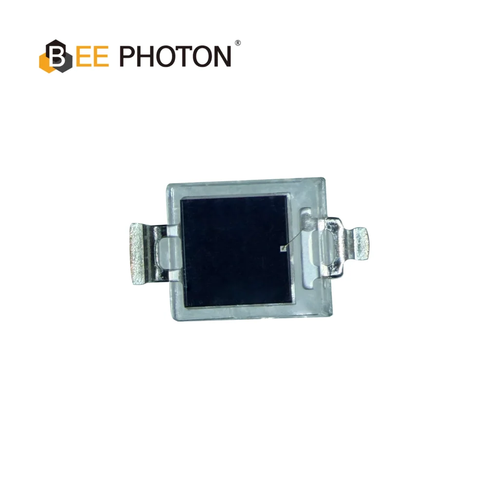
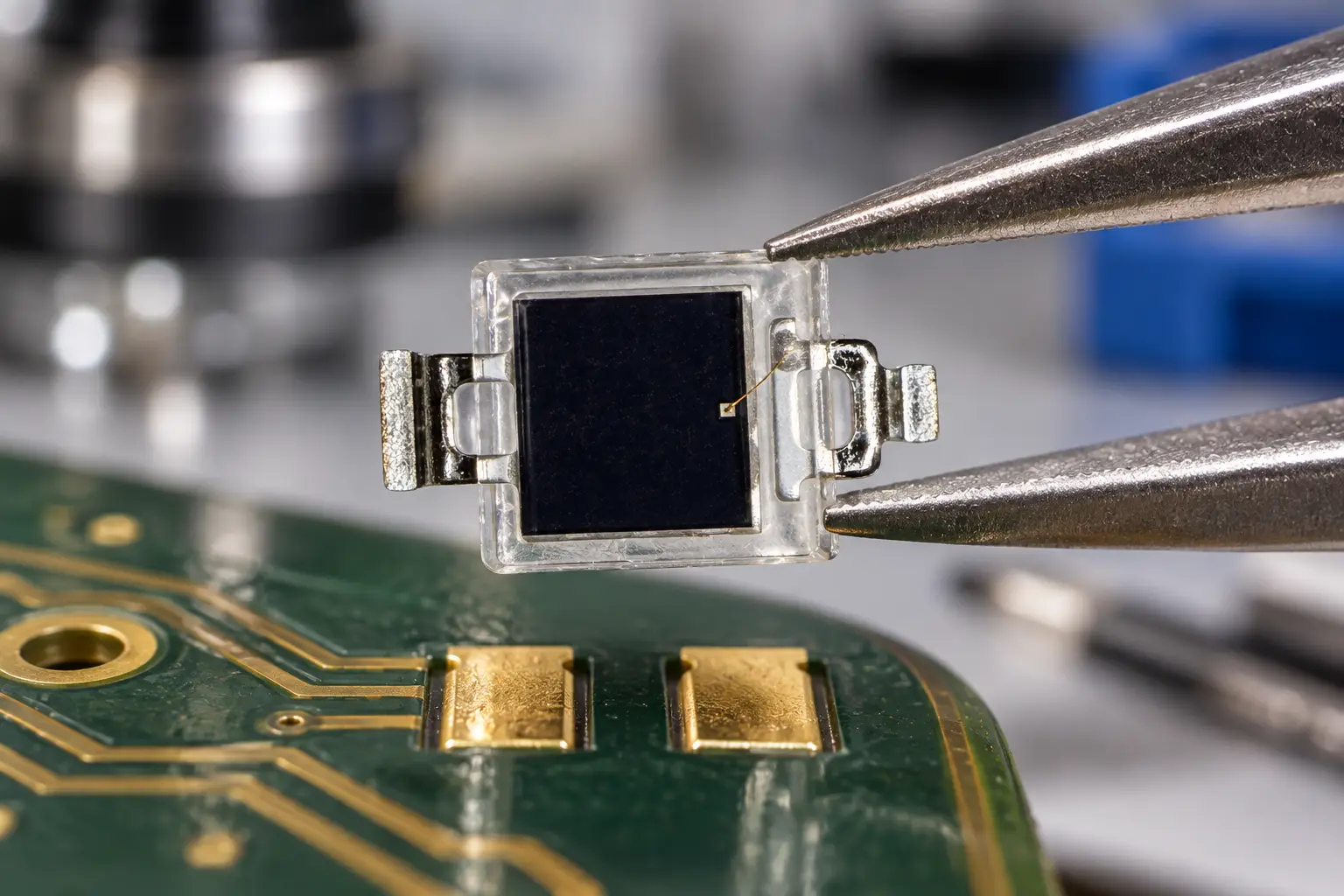
Si PIN photodiode PDCP08 Series PDCP08-501
High-Performance Detection: The PDCP08-501 is a high-speed Silicon PIN Photodiode with a transparent window.
Key Specs: Featuring a 2.9×2.9mm active area, this PIN photodiode offers low dark current and high responsivity, making it an ideal sensor for general optical switches and light detection systems.
Frequently Asked Questions (FAQ)
Why choose a fast response PIN diode over an Avalanche Photodiode (APD) on conveyors?
While Avalanche Photodiodes (APDs) offer internal current gain and sub-nanosecond response, they are generally impractical for industrial conveyor sorting. APDs need high bias voltages (often 100V to 300V+), are expensive, and exhibit severe temperature gain sensitivity requiring complex compensation. A quality fast response PIN diode operates from standard 5V to 24V DC industrial rails, stays thermally stable across factory temperatures (-20°C to +70°C), and easily delivers the sub-0.15 µs speeds needed for sorting lines at a fraction of the cost.
How much reverse bias voltage is ideal for a fast response PIN diode?
For most high-speed sorting sensors, a reverse bias between 5V and 15V hits the sweet spot. This voltage fully depletes the intrinsic layer, dropping junction capacitance (Cj) to its baseline specification and allowing photogenerated carriers to drift at maximum saturation velocity. Running beyond 20V yields diminishing returns while gradually increasing thermal dark current. Always verify the maximum reverse breakdown voltage (V_BR) on your fast response PIN diode datasheet before setting your bias rail.
Does black daylight-filtering epoxy reduce near-infrared LED signal strength?
Hardly at all. The black epoxy used on components like our PDCP08-511 is engineered as an optical long-pass filter. It aggressively rejects visible light (400 nm to 700 nm) while maintaining 85% to 92% transmission across the near-infrared band (850 nm to 950 nm). When paired with common 850 nm or 880 nm infrared emitters, optical signal attenuation is negligible, while ambient noise reduction is massive.
What is the most effective bench method to measure fast response PIN diode rise time?
Connect the fast response PIN diode in series with a 50-ohm coaxial cable terminated directly into the 50-ohm input of an oscilloscope with at least 200 MHz bandwidth. Power the photodiode using a battery or clean linear regulator to apply reverse bias. Pulse an 850 nm laser diode or ultra-fast LED using a signal generator with sub-5 ns rise times. Terminating into 50 ohms minimizes the RC time constant (tr_RC = 2.2 * 50 * Cj), allowing you to evaluate the true physical transit time and switching performance of your fast response PIN diode on screen.
Upgrade Your High-Speed Conveyor Sensors Today
Sluggish optical response should never limit your conveyor throughput. If your development team is fighting pulse degradation, edge jitter, or ambient factory light trips, upgrading your front end with a dedicated fast response PIN diode will instantly clean up your signal chain.
At BeePhoton, we manufacture, test, and calibrate high-reliability optoelectronic components tailored for demanding automated machinery. Whether you need the daylight-filtering PDCP08-511, the miniature SMD PDCP08-502, or the versatile PDCP08-501, our technical team has the hardware expertise to support your machine vision and sensing roadmap.
- Review complete technical specifications across our catalog on BeePhoton.
- Submit your pulse frequency, belt speed, and package specs via our Contact Page.
- Or email our application engineering team directly at info@photo-detector.com to request engineering samples, optical datasheets, or volume pricing. Let us help you eliminate timing jitter and keep your sorting lines running at peak performance.