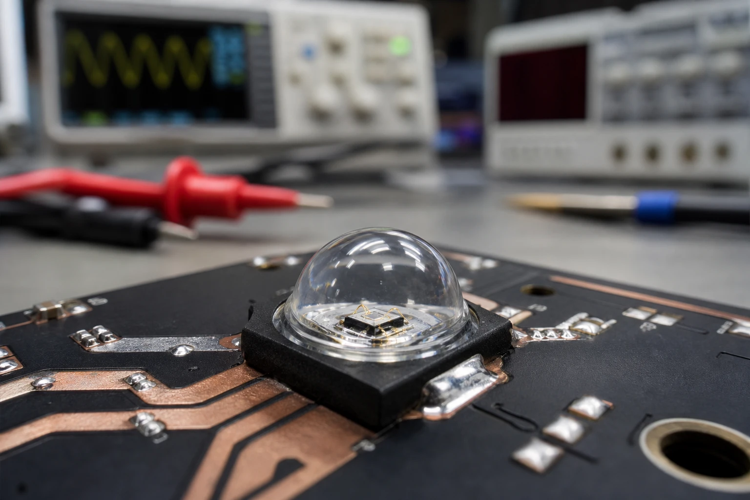
Have you ever spent a late night in the lab, staring at an oscilloscope, trying to figure out why your photoelectric sensor is dropping pulses? You have cranked the receiver gain to its absolute limit, optimized your software filters, and yet, a tiny layer of factory dust or a slight misalignment on the assembly line still breaks the link. It is a classic headache in B2B sensor manufacturing. Most engineers immediately blame the receiver circuit or the software. But to be totally frank with you, the real bottleneck is almost always the light source. Upgrading your optical sensor line with a high-quality high radiance IR LED is the easiest, most cost-effective shortcut to building a bulletproof product that actually survives the factory floor.
Let’s face it, standard emitters simply lack the raw optical punch required for harsh industrial settings. When you are designing sensors for high-speed packaging, automated sorting, or safety barriers, you cannot afford weak signals. Swapping your cheap light sources for a dedicated high radiance IR LED can turn a finicky, temperamental design into an industrial-grade champion. Let’s walk through the actual physics, the dirty secrets of the semiconductor industry, and how to design a circuit that squeezes every last drop of performance out of these emitters.
The Optical Core: What Sets a High Radiance IR LED Apart?
When purchasing managers look at a datasheet, they almost always make the same rookie mistake. They compare “total radiant flux” (measured in milliwatts) and choose the cheapest option that meets their raw power spec. They assume that if two LEDs both spit out 50mW of total optical power, they will perform identically in the field. This is completely wrong, and understanding why is key to seeing the value of a high radiance IR LED.
A standard IR LED is essentially a lightbulb. It throws its light in a wide, lazy arc—often 60 to 120 degrees. This is great if you are trying to flood a room with infrared light for a security camera, but it is a disaster for a precision optical sensor. Most of that light is wasted, bouncing off surrounding machinery and creating optical noise.
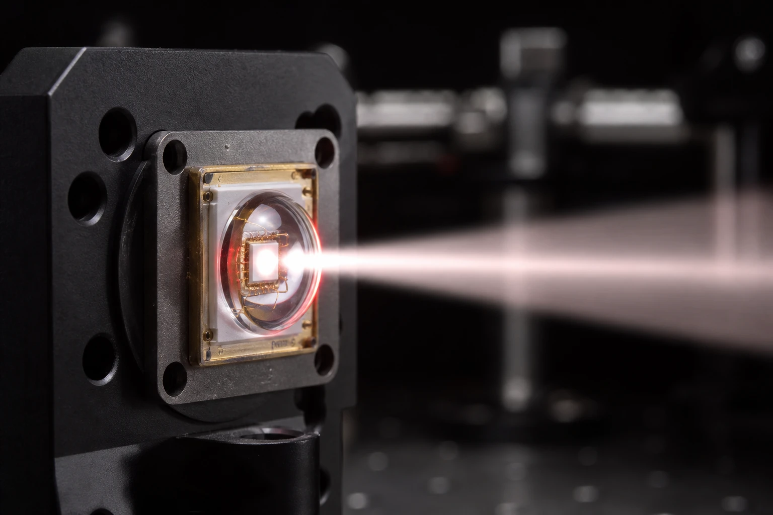
In contrast, a high radiance IR LED acts like a tactical spotlight. It packs that exact same 50mW of optical energy into a very narrow solid angle. Instead of measuring total flux, optical engineers focus on radiant intensity, which is measured in milliwatts per steradian (mW/sr).
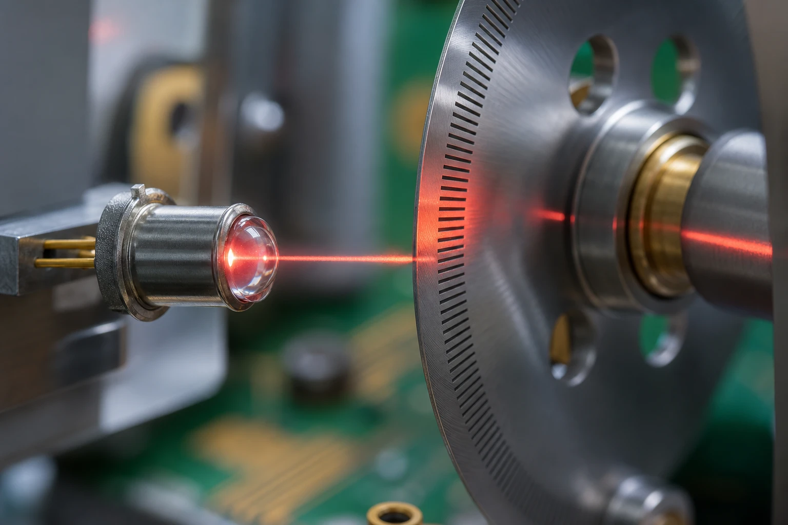
By concentrating the light into a tight, highly directional cone, a high radiance IR LED ensures that the maximum amount of photons actually hit your receiver photodiode. This means you get an incredibly strong signal at the receiver without having to increase your overall system power consumption. If you want your sensors to pierce through heavy dust, oil mist, or long distances, you need a high-intensity emitter.
850nm NIR LED vs 940nm: The B2B Industrial Reality
If you browse B2B sensor catalogs, you will find a never-ending debate between using 850nm and 940nm wavelengths. Let’s share a highly controversial viewpoint: for indoor industrial sensors, 940nm is highly overrated. Many manufacturers use 940nm simply because it is “completely invisible” to the human eye, which makes it popular for consumer electronics or covert security. But for B2B sensor manufacturing, choosing 940nm often destroys your optical link budget.
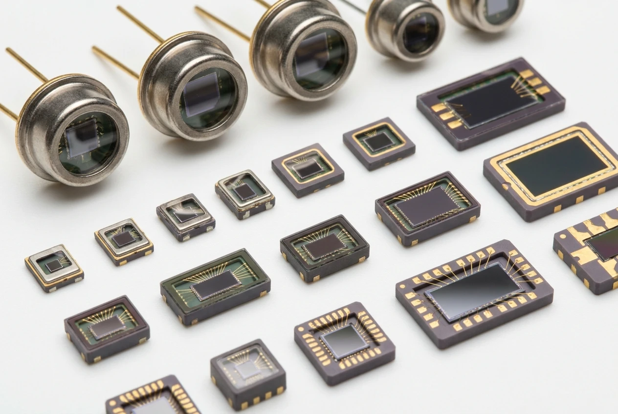
Here is why. Standard silicon photodiodes and phototransistors—the kind you actually use to build affordable receivers—have a spectral sensitivity curve that peaks right around 850nm. At 850nm, a standard silicon PIN photodiode typically boasts a responsivity of around 0.55 Amps per Watt (A/W). When you drop down to 940nm, that responsivity plunges to about 0.35 A/W.
Now, combine that drop in receiver sensitivity with a weak, wide-angle emitter, and your sensor range is cut in half. By upgrading to an 850nm high radiance IR LED, you are aligning your emitter’s output perfectly with the peak quantum efficiency of your silicon detector. This pairing gives you a massive boost in signal-to-noise ratio (SNR) right out of the gate. You will definately notice the difference in performance on day one.
Plus, 850nm light does have a very faint, dull red glow if you look directly at the emitter in a dark room. Some compliance lawyers get nervous about this, but in industrial environments, nobody cares. The massive performance upgrade of an 850nm high radiance IR LED easily outweighs any minor aesthetic preference for total invisibility.
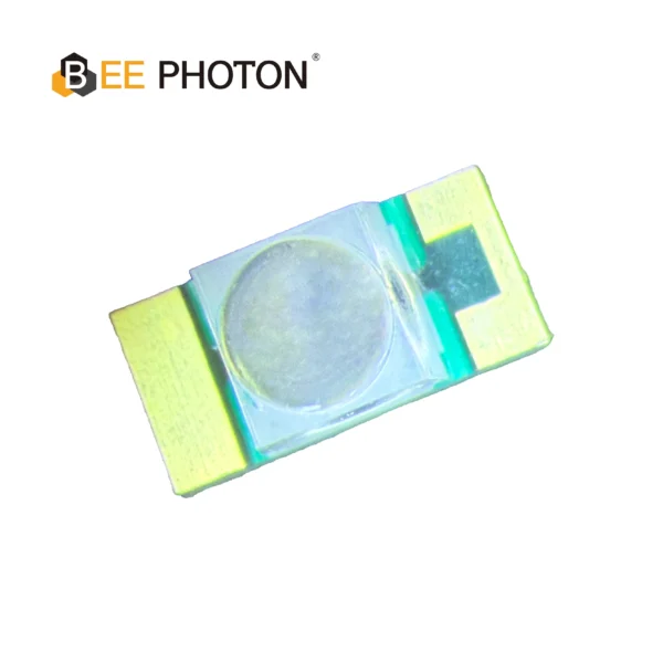
NIR-LED E850-25-001-L20
Der E850-25-001-L20 ist ein Hochleistungs 855nm NIR-LED entwickelt für anspruchsvolle industrielle Anwendungen. Hergestellt von Bee Photon, ist dieses Infrarotstrahler hat einen engen Abstrahlwinkel von 20 Grad und liefert eine hohe Strahlungsintensität von 25 mW/sr, die für Präzisionsmessungen geeignet ist. Das robuste Design sorgt für hohe Zuverlässigkeit und gleichbleibende Leistung über einen weiten Betriebstemperaturbereich.
The B2B Sensor Manufacturing Insider Secrets
Let’s talk about some industry secrets that LED manufacturers do not want you to know. If you are sourcing components for a high-volume B2B sensor manufacturing run, you will quickly realize that not all datasheets are created equal.
Many low-cost suppliers write their specifications based on unrealistic lab conditions. For example, they might claim a high radiant intensity, but if you read the fine print, that measurement was taken with a 10-microsecond pulse at a 0.1% duty cycle under liquid nitrogen cooling. If you try to run that same LED in a real factory at 50 degrees Celsius, its output will drop by half within minutes.
When you source a high radiance IR LED from a reputable brand like BeePhoton, you are paying for thermal stability and packaging quality. Reliable suppliers test their emitters under continuous-use scenarios and provide detailed thermal derating curves.
Another industry secret is die sorting. When LEDs are manufactured on a silicon wafer, the chips in the center of the wafer always perform better than those on the edges. Premium suppliers bin their chips tightly, ensuring that when you buy a high radiance IR LED, you get consistent output from batch to batch. Cheap suppliers will mix different bins together, meaning your production line will struggle with erratic sensor range calibration issues from one week to the next.
Technical Math: Calculating the Real-World Link Budget
Let’s write out some of the actual math you need to design your system. Don’t worry, we won’t use complex LaTeX code that ruins your layout; we will keep it simple and readable.
To calculate how much optical power actually hits your detector, you need to find the solid angle (Omega) of your emitter’s beam.
The formula for the solid angle of a cone of light is:
Solid Angle (Omega) = 2 * pi * (1 – cos(theta / 2))
Wo:
- pi is approximately 3.1416
- theta is the full width at half maximum (FWHM) beam angle of your LED
Let’s say you have a standard LED with a 30-degree beam angle, and you are upgrading to a high radiance IR LED with a tight 18-degree beam angle, such as the BeePhoton E850-180-201L4.
Let’s calculate the solid angle for the standard 30-degree LED:
Omega_standard = 2 * 3.1416 * (1 – cos(30 / 2))
Omega_standard = 6.2832 * (1 – cos(15))
Omega_standard = 6.2832 * (1 – 0.9659)
Omega_standard = 6.2832 * 0.0341 = 0.2143 steradians
Now let’s calculate the solid angle for our 18-degree high radiance IR LED:
Omega_high_radiance = 2 * 3.1416 * (1 – cos(18 / 2))
Omega_high_radiance = 6.2832 * (1 – cos(9))
Omega_high_radiance = 6.2832 * (1 – 0.9877)
Omega_high_radiance = 6.2832 * 0.0123 = 0.0773 steradians
If both LEDs are driven at a current that produces 40mW of total radiant flux, let’s see how much radiant intensity (I) we get.
The basic formula is:
Radiant Intensity (I) = Radiant Flux / Solid Angle
For the standard LED:
I_standard = 40mW / 0.2143 sr = 186.6 mW/sr
For the high radiance IR LED:
I_high_radiance = 40mW / 0.0773 sr = 517.4 mW/sr
By upgrading to the tighter high radiance IR LED, your peak optical intensity at the center of the beam increases by nearly three times, even though you are using the exact same amount of electrical current. That is the magic of optical design.
Driving Circuits: Pushing a High Radiance IR LED to the Limit
You cannot simply connect a high radiance IR LED to a standard digital output pin on a microcontroller and expect it to work. These high-performance emitters require a robust analog driving stage to handle high peak currents safely.
To design a high-frequency pulsed driving circuit, you should use an N-channel MOSFET as a low-side switch. Here is a step-by-step breakdown of how to build this circuit on your PCB:
- Connect the positive voltage rail (V_drive, usually 5V or 12V) to a high-quality ceramic decoupling capacitor (10uF in parallel with 100nF) placed as close to the LED anode as possible. This prevents voltage sag during high-current pulses.
- Connect the LED anode to the voltage rail.
- Connect the LED cathode to a low-inductance power resistor (R_limit) to limit the peak current.
- Connect the other side of R_limit to the Drain pin of your N-channel MOSFET.
- Connect the Source pin of the MOSFET directly to a solid ground plane.
- Connect your microcontroller’s PWM pin to the Gate of the MOSFET through a small 47-ohm resistor to suppress high-frequency ringing.
Durch das Pulsieren Ihres high radiance IR LED with a low duty cycle (for example, a 10-microsecond pulse every 1 millisecond, which is a 1% duty cycle), you can push the peak current up to 1 Amp or more without overheating the chip. This gives your sensor a massive burst of light that can easily pierce through layers of dirt and oil on a factory conveyor belt.
NIR-LED E850-180-201L4
Die E850-180-201L4 ist eine leistungsstarke 850nm NIR-LED für die industrielle Präzisionsmessung entwickelt. Hergestellt von Bienen-Photon, Dieser Infrarot-Strahler ist auf hohe Leuchtkraft und außergewöhnliche Stabilität ausgelegt und damit die ideale Lichtquelle für anspruchsvolle Automatisierungsumgebungen.
Dealing with Thermal Runaway and Packgaging Weaknesses
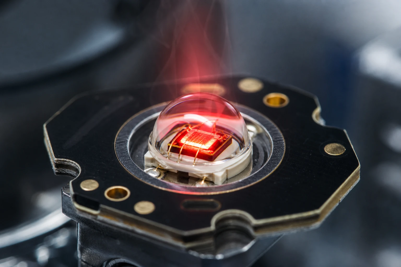
Let’s address another critical engineering challenge: thermal management. Even though a high radiance IR LED is highly efficient, a significant portion of its electrical energy is still wasted as heat.
If you do not design your PCB properly, the emitter will suffer from thermal runaway. As the semiconductor material heats up, its forward voltage drops, which causes it to draw more current if driven by a constant voltage. More current means more heat, creating a vicious cycle that will quickly destroy your high radiance IR LED.
To prevent this, you should always drive your high radiance IR LED using a constant-current circuit or a tightly controlled current-limiting resistor.
Furthermore, you need to pay close attention to your PCB layout. Standard FR4 glass-epoxy PCBs are terrible thermal conductors. When laying out your board, you must place large copper pours around the LED’s cathode pin, as this is usually the main thermal path out of the chip. Stitch this copper pour to an internal ground plane using multiple thermal vias.
Eine hohe Qualität high radiance IR LED that is kept cool will maintain its peak wavelength and optical output for decades, saving your company thousands of dollars in warranty claims and field replacements.
The E850-180-201L4 Deep Dive: A Real Upgrade Optical Sensor Case
Let’s look at a concrete example of an emitter designed specifically to solve these industrial challenges: the BeePhoton E850-180-201L4.
This particular high radiance IR LED was engineered from the ground up for high-reliability B2B applications. It features an integrated optical dome lens that focuses the light into a tight, symmetrical 18-degree beam. This eliminates the need for expensive external plastic lenses on your sensor housing, which often turn yellow and degrade over time when exposed to harsh factory lighting and cleaning chemicals.
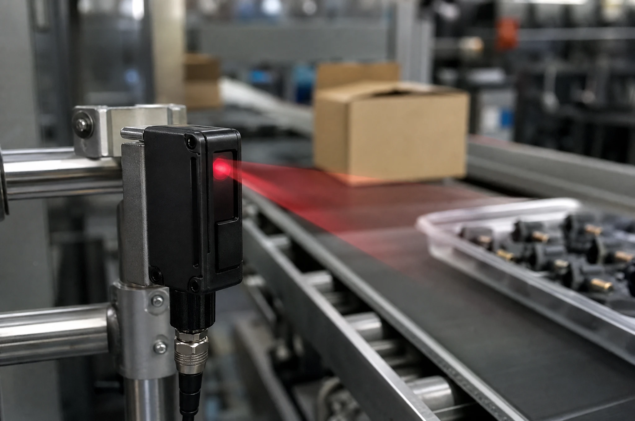
We recently saw a B2B manufacturer upgrade their optical sensor line using the E850-180-201L4 high radiance IR LED. They were building safety light curtains for heavy stamping presses. Their old design used generic, wide-angle 850nm emitters, and they were plagued by false triggers caused by mechanical vibrations that slightly misaligned the emitter and receiver bars.
By switching to the E850-180-201L4 high radiance IR LED, they were able to project a highly concentrated beam across a 10-meter span. The intense, focused light meant that even if the mounting brackets vibrated by a few degrees, the receiver photodiode still recieved plenty of optical signal to stay locked on. The upgrade saved their product line from a costly recall and restored their customers’ trust.
Real-World Performance Comparison
To help you choose the right emitter for your B2B sensor manufacturing needs, let’s look at how a premium high radiance IR LED compares to other common optical light sources on the market.
| Leistungsmetrik | Standard 850nm LED | Premium High Radiance IR LED (e.g., E850-180-201L4) | Generic 940nm LED | High-Power Flood LED |
|---|---|---|---|---|
| Peak-Wellenlänge | 850nm | 850nm | 940nm | 850nm |
| Typical Beam Angle | 60 – 120 degrees | 15 – 20 degrees | 45 – 60 degrees | 120 degrees |
| Strahlungsintensität | ~15 mW/sr | >150 mW/sr (at 100mA) | ~10 mW/sr | ~40 mW/sr |
| Silicon PD Matching | Excellent (~0.55 A/W) | Perfect (~0.58 A/W) | Poor (~0.35 A/W) | Ausgezeichnet |
| Thermal Resistance | >150 K/W | <45 K/W (Very Low) | >180 K/W | <15 K/W |
| Relative Stückkosten | Niedrig ($) | Mittel ($$) | Niedrig ($) | High ($$$) |
As you can see, using a specialized high radiance IR LED provides an incredible boost in radiant intensity without the massive thermal footprint and high cost of a massive high-power flood LED. It is the sweet spot for precision optical switches, safety light barriers, and high-speed B2B sensor applications.
Practical Troubleshooting: Aligning Your High Radiance IR LED
Once you make the switch to a high radiance IR LED, you might run into a few classic integration challenges. Here is how to troubleshoot them like a seasoned pro on your production line.
First, let’s look at mechanical alignment. Because a high radiance IR LED throws such a tight beam, your assembly line tolerances must be spot-on. If your plastic housing is slightly warped, the beam might miss the receiver photodiode completely at longer distances. To fix this, we recommend designing simple alignment tabs directly into your sensor’s plastic injection molds to lock the LED and receiver in perfect alignment.
Second, watch out for receiver saturation. If a target object moves very close to the sensor, the immense optical power of the high radiance IR LED can flood the photodiode, causing the receiver’s amplifier circuit to clip. This can make the sensor “blind” to objects that are too close. You can easily solve this in software by using a variable duty-cycle drive—meaning you drop the LED current when you detect that the target is nearby.
Finally, keep an eye on optical crosstalk. Because the output of a high radiance IR LED is so strong, any light leaking inside the sensor’s housing can cause false triggers. Always use a physical, opaque black plastic barrier to isolate the emitter cavity from the receiver cavity on your PCB.

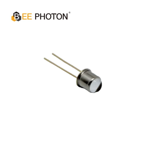
Lichtquelle LED-Serie E850-30-101
Die E850-30-101 ist ein hochstabiler 850nm-Infrarotstrahler im robusten 3mm-Dual-Inline-Package-LED-Format für einfache Leiterplattenmontage und überragende Haltbarkeit. Mit einem schmalen Abstrahlwinkel von 20° und einer Strahlungsintensität von 30 mW liefert diese Dual In-line Package LED eine präzise und helle Leistung und ist damit die ideale Lichtquelle für optische Schalter, industrielle Sensorik und anspruchsvolle Automatisierungsanwendungen.
FAQ: Critical Engineering Questions on High Radiance IR LED Emitters
Can I directly replace my existing LED with a high radiance IR LED?
Yes, in most cases, you can physically drop a high radiance IR LED onto your current PCB footprint, especially if you are using standard surface-mount or through-hole packages. However, to fully unlock the benefits of your new high radiance IR LED, you should review your current limiting resistor. You might want to decrease the resistance to drive the new LED at its optimal peak current, or adjust your receiver’s amplifier gain to prevent saturation.
Why is an 850nm high radiance IR LED better than a 940nm option for industrial automation?
The primary reason is receiver performance. Standard silicon sensors are significantly more sensitive to 850nm light than 940nm light. When you pair an 850nm high radiance IR LED with a silicon PIN photodiode, you get a much higher signal-to-noise ratio. This allows your sensor to operate reliably over longer distances and through much dirtier environments than a 940nm system ever could.
How does temperature drift affect a high radiance IR LED over years of use?
As an LED ages and heats up, its peak wavelength will slowly shift upward (usually by about 0.25 nm per degree Celsius), and its overall optical output will slowly degrade. However, a premium high radiance IR LED is designed with high-quality packaging and low thermal resistance to minimize this degradation. If you keep the junction temperature low through proper PCB copper heatsinking, your emitter will easily maintain stable performance for over 100,000 hours of continuous operation.
Ready to Upgrade? Let’s Get It Done
If you are tired of dealing with weak optical signals, field failures, and complaining customers, it is time to take action. Upgrading your sensor line with a high-performance high radiance IR LED is the single fastest way to transform your product from a bench prototype into a rugged, industrial-grade solution.
Unter BeePhoton, we have spent years engineering high-performance optical components that thrive in the toughest industrial environments. Whether you need custom photodetectors or cutting-edge infrared light sources, our team has the real-world experience to help you succeed.
We encourage you to explore our comprehensive LED light source catalog to find the perfect emitter match for your project. If you have a specific technical challenge or need custom packaging, please head over to our Kontaktseite and get in touch with our engineering team directly. You can also send an email to info@photo-detector.com to request samples, ask for a quote, or get a detailed review of your current schematic. Let’s work together to build a faster, stronger, and more reliable sensor line today.