If you have ever spent any time on a modern factory floor, you know that things move at a crazy pace. Whether you are running a high-speed beverage bottling line, etching serial numbers onto automotive parts, or micro-machining semiconductors, speed is your best friend and your worst enemy. If your laser marking machine slips by even a fraction of a millimeter, you end up with blurred QR codes, ruined parts, and a mountain of wasted scrap.
If you don’t have a reliable laser marking scanner position sensor, your high-speed line is basically running blind.
A lot of system integrators and laser machine OEMs spend weeks tweaking their digital controller settings, trying to eliminate jitter and drift. But here is the honest truth: the root problem usually is not in your digital software loop. It is in the analog feedback hardware. At the heart of this loop is the laser marking scanner position sensor. If this sensor is noisy, temperature-sensitive, or fragile, your entire marking system will fail under real-world factory conditions. Selecting the right laser marking scanner position sensor is critical if you want to achieve microradian-level precision without constant maintenance shutdowns.
In this guide, we will break down why the laser marking scanner position sensor is the unsung hero of industrial marking heads, how the underlying physics of optical feedback works, and why choosing high-durability silicon components is the key to surviving high-frequency vibrations.
Inside the Galvo Scanner: How Optical Position Feedback Works
Most high-speed industrial laser markers use galvanometer scanners—commonly known as galvos—to position the laser beam. Unlike a standard electric motor that spins in continuous circles, a galvo rotates back and forth within a highly restricted mechanical range, usually around plus or minus 15 to 20 degrees. It has to accelerate, stop, and reverse directions thousands of times per minute. To keep these rapid oscillations tight, the driver board needs to know the exact mirror angle at any given microsecond. That’s where the laser marking scanner position sensor steps in.
How does a laser marking scanner position sensor do this? Many classic, high-performance galvos rely on an optical analog feedback mechanism. The mechanical setup is elegant, solid-state, and incredibly lightweight:
- An infrared LED inside the scanner motor housing projects a steady beam of light.
- A tiny, lightweight light-blocking paddle (often called a shutter or mask) is mounted directly to the rotating motor rotor shaft.
- As the shaft rotates, the paddle blocks more or less light, casting a moving shadow.
- A specialized silicon photodetector catches this shadow and translates the changing light levels into analog electrical currents.
Let’s look at the math that makes a laser marking scanner position sensor so precise. The sensor relies on a differential optical measurement. Let’s say we are using a dual-channel photodetector chip where the light-blocking paddle casts a shadow across two separate photosensitive segments, Segment A and Segment B. As the rotor turns, the photocurrent coming from Segment A increases while the photocurrent from Segment B decreases.
To calculate the precise angular position, the feedback electronics run this normalized differential formula:
Position Output = (Current_A - Current_B) / (Current_A + Current_B)
This simple calculation is beautiful. By dividing the difference between the two currents by their sum, the output signal becomes completely independent of the total light intensity. If the internal LED dims slightly as it ages, or if the power supply has a bit of voltage ripple, the sum and the difference scale proportionally, leaving the final position calculation unaffected.
It means your laser marking scanner position sensor maintains its calibration even as components age. If your laser marking scanner position sensor didn’t use this differential trick, you’d have to recalibrate your marking heads every couple of weeks just to keep the markings aligned. When you buy a high-quality laser marking scanner position sensor, you’re paying for this mathematical stability.
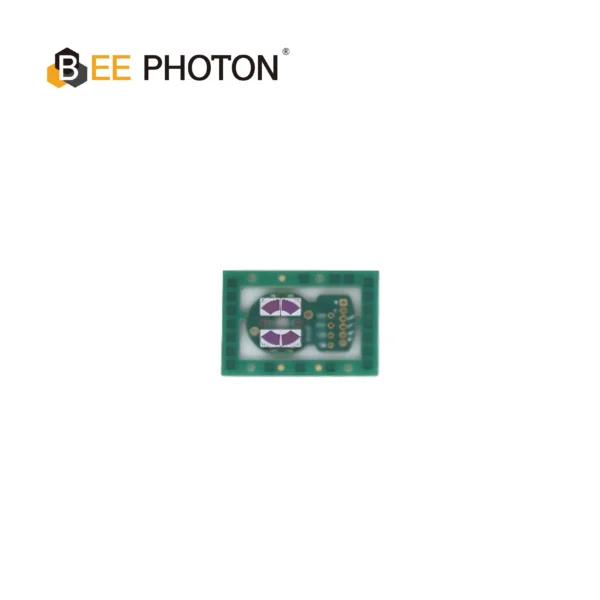
Si PIN photodiodes for Galvo PDC-2C3432-NIR-B
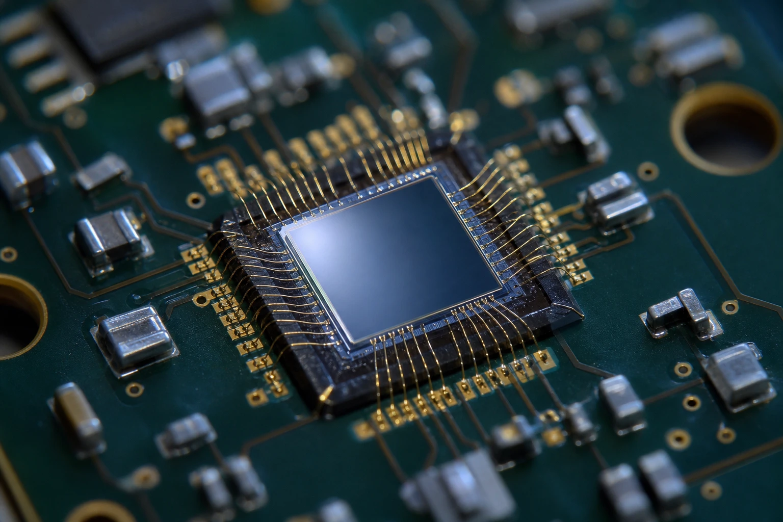
The PDC-2C3432-NIR-B is a specialized segmented PIN photodiode chip engineered for precise differential position feedback in high-speed galvanometer scanners. Integrating this dual-channel segmented PIN photodiode chip allows systems to obtain accurate angular tracking with minimal signal noise.
The Big Debate: Analog Optical PDs vs. Digital Encoders
If you talk to some engineering purists, they will tell you that digital encoders are the future of laser marking. They will argue that digital encoders offer higher resolution and are immune to analog line noise. But if we are being real about B2B factory operations, digital encoders can be a major headache in high-vibration environments.
Digital encoders usually rely on glass or metal scale discs etched with microscopic lines. When a galvo is marking characters at high speeds, it undergoes immense accelerations—sometimes up to 50G or more. Under these high-frequency vibrations, those delicate glass scales are prone to micro-cracking, misaligning, or gathering fine industrial dust that blocks the optical readhead. If your laser marking scanner position sensor relies on a fragile digital scale, one bad jolt can stop your entire line.
An optical laser marking scanner position sensor using silicon photodiodes, on the other hand, is a solid-state beast. There are no microscopic lines to align. It is just a flat piece of silicon catching a shadow. The physical paddle does not touch the sensor, meaning there is zero friction to wear out over time. If your machine is shaking at 50G accelerations, a silicon-based laser marking scanner position sensor won’t skip a beat.
There is also the issue of rotor mass. Digital encoder discs add physical weight to the rotating shaft. In galvo design, rotor inertia is the enemy of speed. A heavier rotor means your galvo takes longer to accelerate and decelerate, which slows down your marking cycle times. That’s why a photodetector-based laser marking scanner position sensor is still the undisputed king of high-speed marking. It keeps the rotor assembly incredibly light, maximizing your system’s frequency response. Choosing a lightweight, robust laser marking scanner position sensor is simply the smart move for system integrators who need 24/7 reliability in harsh industrial environments.
The Silent Killer of Accuracy: Jitter and Dark Current
Let’s discuss a problem that drives laser machine builders crazy: marking jitter. You program a perfect circle into your laser software, but when you look closely at the engraved metal part, the circle has wavy, jagged edges.
The main culprit is electronic noise in the feedback path. If the photodiode chip inside your laser marking scanner position sensor has high dark current, it introduces random thermal noise into the system. Dark current is the tiny electrical current that flows through a photodetector even when there is absolutely zero light hitting it.
When your transimpedance amplifier (TIA) boosts the small feedback current from the laser marking scanner position sensor, it also amplifies this dark current noise. The servo controller gets confused, mistakes this noise for actual mechanical mirror drift, and constantly tries to correct it. That rapid, micro-adjustment is what we call jitter.
To eliminate this, you need a laser marking scanner position sensor built with ultra-low dark current silicon. If you look at high-performance options like the PDC-C2928-NIR-B Si PIN photodiode from BeePhoton, it features a typical dark current of just 5 pA (picoamps) at 10mV bias, combined with a huge 2 Gigaohm shunt resistance. Compare that to cheap, off-the-shelf photodetectors that often have dark currents up to 200 pA or higher. By swapping a noisy diode with a quiet, high-performance chip inside your laser marking scanner position sensor, you can drop your feedback noise floor by over 15 dB. That is the difference between a jagged, sloppy mark and a razor-sharp engraving.
Another critical factor is junction capacitance. High junction capacitance slows down the photodiode’s reaction time. If your laser marking scanner position sensor reacts too slowly, the feedback loop will lag behind the motor, causing overshoot—where the mirror swings past the target angle before snapping back. For high-speed lines, your laser marking scanner position sensor needs a fast rise time. High-performance chips like the PDC-C2928-NIR-B have a rise time of 0.27 microseconds, ensuring your feedback loop is fast enough to handle high-frequency galvo moves.
Sourcing the Right Photodiode Chip for Your Sensor Design
If you are an OEM designing a custom galvo or repairing high-end scanning heads, you have a few options when sourcing the silicon chip for your laser marking scanner position sensor. The choice of chip depends heavily on your target accuracy and bill of materials (BOM) budget.
If you are building premium, high-accuracy systems where zero drift is the goal, you should look at the PDC-C2928-NIR-B Si PIN photodiode. This 940nm PIN photodiode chip is specifically optimized for near-infrared light. Most internal galvo LEDs run at NIR wavelengths (like 850nm to 940nm) because it prevents ambient room lighting from interfering with the position feedback. With its low noise and stable dark current, it is designed to keep your laser marking scanner position sensor running whisper-quiet.
For advanced, high-end differential positioning where you need segmented tracking, a single-channel diode won’t cut it. You need a dual-channel design. A chip like the PDC-2C3432-NIR-B segmented PIN photodiode offers a dual-segment, fan-shaped design. It allows your laser marking scanner position sensor to run a highly accurate differential positioning scheme, catching even the slightest sub-microradian tilt of the motor shaft. It is perfect for advanced, dual-channel analog feedback networks.
On the other hand, if you are designing a cost-sensitive industrial scanner and need to keep your costs down without sacrificing basic stability, you can use a budget-friendly chip like the PDC-C2929 920nm silicon PIN photodiode. It offers a very stable 70 pF junction capacitance and highly consistent response at a much lower price point. It’s a great way to build a reliable laser marking scanner position sensor without overspending on over-engineered components.
Whichever chip you choose, make sure you match the peak spectral sensitivity wavelength with your internal LED emitter. If your LED wavelength does not match the chip’s peak sensitivity, your laser marking scanner position sensor won’t get enough signal, forcing you to turn up your amplifier gain and introducing unwanted noise back into the feedback loop.
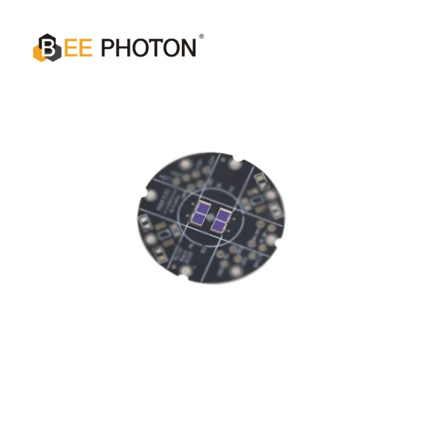
Si PIN photodiodes for Galvo PDC-C2929
The PDC-C2929 is a budget-friendly 920nm silicon PIN photodiode chip. This 920nm silicon PIN photodiode offers stable, cost-effective scanner position tracking.
A Real-World Scenario: Stopping the Line Shutdowns
Let’s step away from the technical datasheets for a second and look at how this plays out on the factory floor. A line integration company we work with was setting up an automated marking station for a major beverage packager. The system was designed to etch expiration dates and batch codes onto aluminum cans moving at a rate of 1,200 cans per minute. The environment was hot, humid, and vibrating constantly from nearby conveyor belts and pneumatic actuators.
Initially, they used a cheap import scan head that featured a basic laser marking scanner position sensor built with generic, high-capacitance photodiodes. Within three weeks of 24/7 operation, the batch codes started to drift. The feedback loop inside the laser marking scanner position sensor couldn’t handle the high-frequency vibrations and the rising ambient heat of the packaging plant. The dark current in their cheap sensor spiked, causing the laser to misalign and write illegible text. The bottling line had to be shut down twice in one week, costing thousands of dollars in lost production time.
The integrator realized they needed a more robust laser marking scanner position sensor. They replaced the internal photodetector chips in their scanning heads with BeePhoton’s PDC-C2928-NIR-B. The difference was immediate. Because of the chip’s low temperature drift and rock-solid 5 pA dark current, the feedback loop became incredibly stable. The new laser marking scanner position sensor kept the laser spot exactly on target, even with the heavy conveyor vibrations. The bottling line has now been running for over eighteen months without a single sensor-related failure. That’s the power of investing in a high-durabiliyt laser marking scanner position sensor from the start.
PD Feedback vs. Digital Encoders: Head-to-Head Comparison
To help you make the right call for your production lines, let’s compare these two core feedback technologies side-by-side. When looking for a laser marking scanner position sensor, you will usually have to choose between these two approaches:
| Key Feature | Photodetector-Based (Analog PD) | Digital Encoder-Based |
|---|---|---|
| Sensor Type | Analog solid-state silicon chip | Digital glass or metal scale |
| Vibration Tolerance | Extremely High (No fragile parts) | Low to Medium (Glass can crack) |
| Rotor Inertia | Ultra-low (Small light-blocking paddle) | Higher (Glass disk adds weight) |
| Feedback Speed | Very High (Analog bandwidth >50kHz) | Limited by sampling clock jitter |
| Cost Profile | Highly cost-effective for OEMs | Expensive |
| Common Wavelengths | 920nm – 940nm NIR | Visible / Laser-diode |
As you can see, if you are looking for a laser marking scanner position sensor that can handle high-frequency vibration and keep your costs down, analog photodetector feedback is almost always the better choice for high-volume B2B manufacturing.
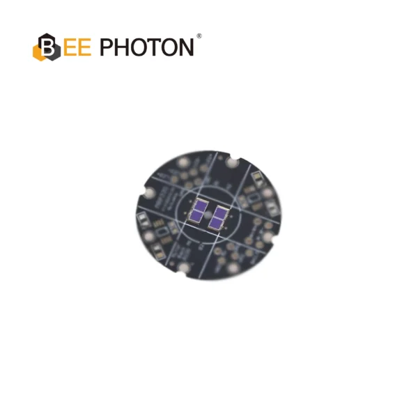
Si PIN photodiodes for Galvo PDC-C2928-NIR-B
Optimize scanning with our 940nm PIN photodiode chip, PDC-C2928-NIR-B. This 940nm PIN photodiode chip ensures precise galvo position sensing and low noise.
FAQ: Optimizing Your Galvo Feedback System
Why is my galvo system losing calibration as the factory warms up?
This is almost always due to temperature drift in your laser marking scanner position sensor. When ambient temperatures rise, the dark current in cheap silicon photodiodes increases exponentially. This extra current mimics actual mirror movement, causing the controller to drift. Using a high-performance, low-drift laser marking scanner position sensor like those built with BeePhoton’s specialized silicon PIN chips helps prevent this thermal drift.
Can I use a standard 850nm LED with a 940nm photodiode chip?
You can, but it is not ideal. While a 940nm chip will still detect 850nm light, its responsivity will be lower. This means your laser marking scanner position sensor will output a weaker signal. To get the best signal-to-noise ratio, try to match your light emitter wavelength with the peak spectral response of your laser marking scanner position sensor’s photodiode.
How do I know if my laser marking scanner position sensor is failing?
Common signs include sudden marking drift, jagged lines (jitter), or a complete loss of control where the mirror swings to its physical limit and stays there. If you suspect your laser marking scanner position sensor is dying, check the differential voltage coming off the photodiode preamp. If it’s flat or highly erratic, it’s time to swap out the sensor chip.
Ready to Upgrade Your Optical Feedback?
In high-volume B2B manufacturing, you can’t afford to run blind. Your laser marking heads are only as good as the feedback loop guiding them. A high-durability laser marking scanner position sensor built with low-noise silicon PIN photodiodes is the key to achieving sharp, consistent marks at speeds over 10,000 mm/s.
Whether you are building a custom scanning head from scratch or trying to optimize an existing system, the choice of your laser marking scanner position sensor is the single most important decision you’ll make. We often see engineers spend weeks tweaking their servo loop parameters when the real issue is just a low-quality laser marking scanner position sensor. At the end of the day, a laser marking scanner position sensor is the heartbeat of your closed-loop galvo scanner. If you don’t have a reliable laser marking scanner position sensor, you’re just throwing money away on downtime and scrap.
Don’t let cheap sensor componets slow down your production. If you want to optimize your scanner designs or source high-durabiliyt components for your next-generation marking heads, contact BeePhoton today or drop us an email at info@photo-detector.com to get a custom quote and engineering support!