If you have spent any time in motion control, you know how a bad Rotary Encoder LED choice can completely destroy your sensor’s accuracy. Sometime, you spend days tweaking your pull-up resistors, shielding the cabling, or filtering the power lines, but the signal still looks like a messy saw-tooth wave. Many optical engineers overlook the source of light itself. Designing with a cheap, generic Rotary Encoder LED is a massive mistake. When selecting your Rotary Encoder LED, you cannot treat it as a simple flashlight.
This article will tear down the differences between a 4-degree Rotary Encoder LED and wider alternatives. We will look at the exact optical mechanics of the Rotary Encoder LED, the mathematics of shadow projection, and why the typical 4-degree narrow beam is essential for high-resolution industrial encoders.
The Optical Path: Why the Rotary Encoder LED Matters
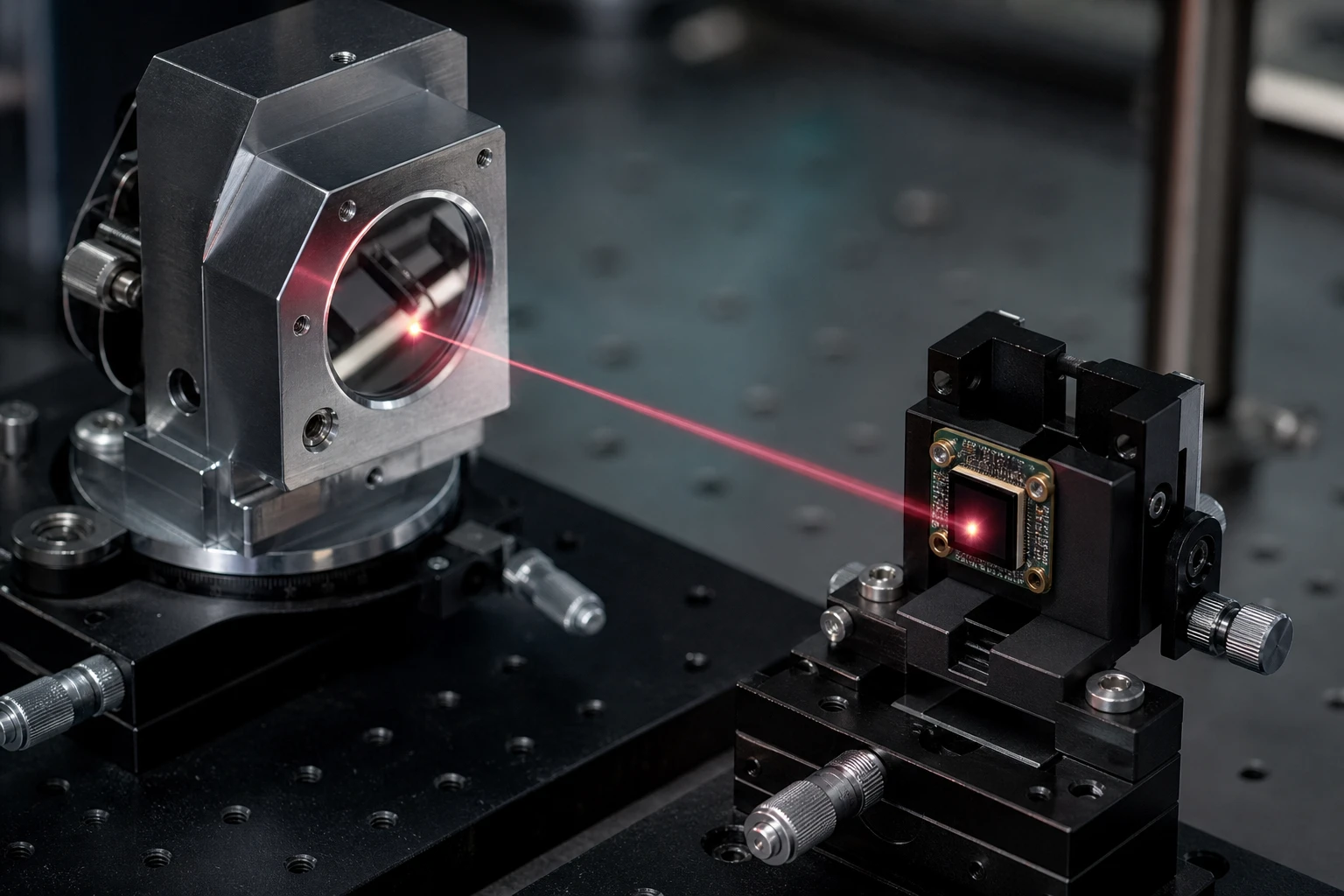
The role of a Rotary Encoder LED in an optical rotary sensor light is to throw parallel light through the moving code wheel slits. This allows the photodetector array to read clear, distinct pulses of light and shadow. But light naturally wants to spread out. If your Rotary Encoder LED is emitting light with a wide divergence, the light rays leave the lens at various angles, casting overlapping shadows of the slits.
You can measure how your Rotary Encoder LED behaves using a simple formula that optical engineers use to design reading heads:
w = d + 2 * L * tan(theta / 2)
Where:
- w is the final light spot width on the photodetector plane.
- d is the active emitting area of the Rotary Encoder LED chip.
- L is the physical gap (air gap) between the LED lens tip and the code wheel.
- theta is the beam angle (divergence angle) of the light source.
Let’s look at how this math plays out in a real design. Imagine a high-resolution encoder where the emission spot size of our LED chip is 0.15 mm, and the air gap is 1.5 mm.
With a 4-degree Rotary Encoder LED, the math looks like this:
w = 0.15 + 2 * 1.5 * tan(2 degrees)
w = 0.15 + 3 * 0.0349
w = 0.2547 mm
The spot size only expands to about 0.25 mm. This keeps the light tight and parallel as it passes through the slits, casting sharp, high-contrast shadows onto your photodetector array.
Now, let’s compare this to a 10-degree Rotary Encoder LED under the same conditions:
w = 0.15 + 2 * 1.5 * tan(5 degrees)
w = 0.15 + 3 * 0.0875
w = 0.4125 mm
With a 10-degree model, the spot size has almost doubled. The edges of the shadows are now fuzzy. If you push the angle to 20 degrees, the spot size balloons to 0.68 mm, which completely blurs the shadow edges. When you upgrade to a 4-degree Rotary Encoder LED, you prevent this shadow blur and keep your signals clean.
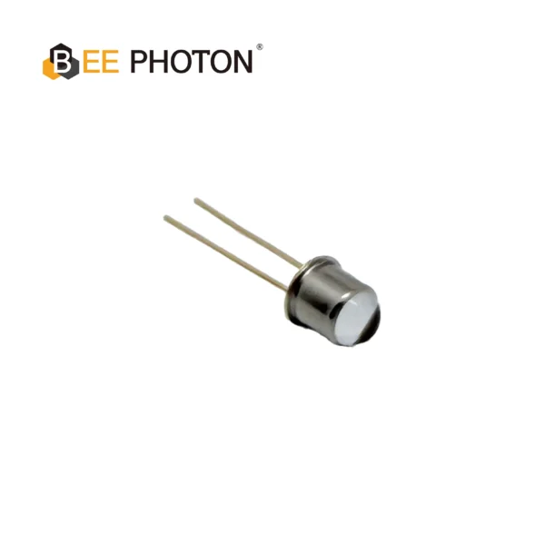
NIR LED E850-25-001-L20
The E850-25-001-L20 is a high-performance 855nm NIR LED designed for demanding industrial applications. Manufactured by Bee Photon, this infrared emitter features a narrow 20-degree emission angle, delivering high radiant intensity of 25mW/sr tailored for precision sensing. Its robust design ensures high reliability and consistent output over a wide operating temperature range.
Understanding the Angle of Half Intensity in a Rotary Encoder LED
If you look at a datasheet, you will see a specification called the angle of half intensity. Understanding the angle of half intensity in a Rotary Encoder LED is critical for predicting how much stray light will spill onto adjacent sensor channels. For any standard Rotary Encoder LED, this is the angle where the light’s power drops to exactly half of its peak intensity on the central optical axis.
For a 4-degree beam angle, this angle of half intensity is typically written as plus or minus 2 degrees. This means that once you step just 2 degrees off the center axis, the light power drops off a cliff.
This steep drop-off is exactly what you want. Inside a high-quality focused emission diode, the optical lens is designed with tight manufacturing tolerances. This ensures that the Rotary Encoder LED behaves like a pin-point light source rather than a floodlight.
Why a 4-Degree Rotary Encoder LED Wins the Shootout
When comparing different beam angles, the difference is night and day. If you are building high-resolution industrial encoders, you simply cannot afford the signal degradation that comes with wider beams.
Our table below compares various Rotary Encoder LED specifications to help you visualize the trade-offs:
| Parameter | 4-Degree Rotary Encoder LED | 10-Degree Rotary Encoder LED | 20-Degree Rotary Encoder LED |
|---|---|---|---|
| Beam Type | Tight, parallel, collimated | Moderate divergence | Highly divergent |
| Half Intensity Angle | ±2.0 degrees | ±5.0 degrees | ±10.0 degrees |
| Spot Spread at 1.5mm Gap | 0.25 mm | 0.41 mm | 0.68 mm |
| Signal Contrast Ratio | Excellent (above 90%) | Moderate (60% to 70%) | Poor (under 40%) |
| Crosstalk Risk | Extremely Low | Moderate to High | Critical |
| Speed Performance | Reliable up to 10k+ RPM | Prone to phase jitter | Unusable at high speeds |
| Best Suited Resolution | High & Ultra-High | Standard | Low / Simple Switches |
The optical gap is critical for any Rotary Encoder LED. If your Rotary Encoder LED is too wide, the light spreads out and bleeds into neighboring photodetector channels. This table clearly shows why a 4-degree angle is the industry standard for high-speed, high-resolution applications.
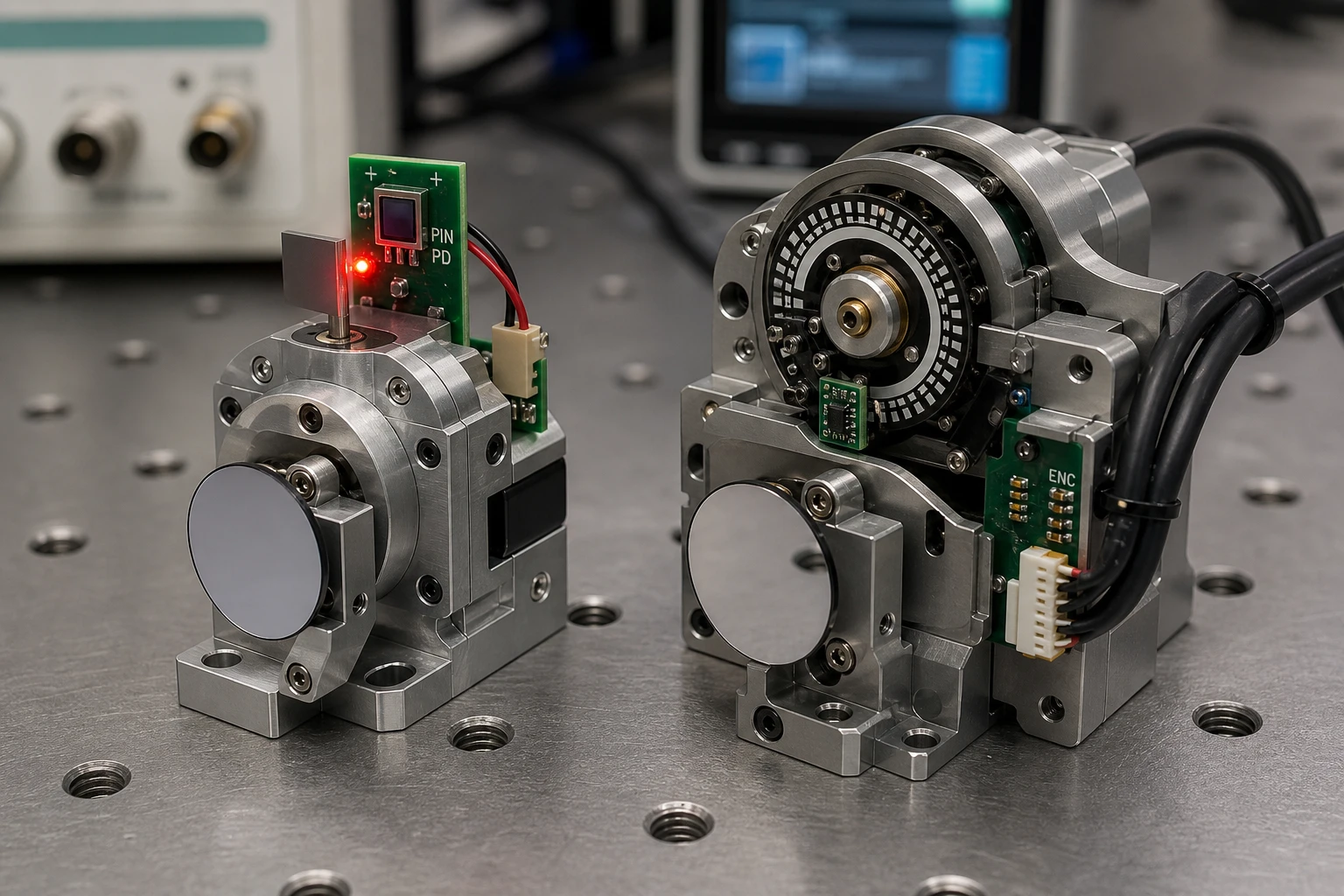
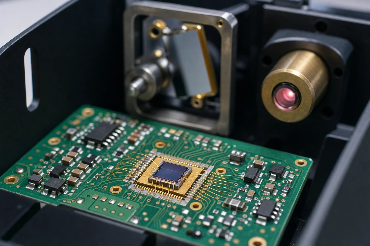
Inside the Optical Path: How a Rotary Encoder LED Reads the Disc
Let’s look at how a Rotary Encoder LED interacts with the code wheel. As the code wheel spins, the alternating open and closed slits modulate the light. The photodetector measures this modulation to calculate position and speed.
The contrast ratio of your Rotary Encoder LED setup can be calculated using this formula:
M = (I_max – I_min) / (I_max + I_min)
Where:
- M is the signal contrast ratio.
- I_max is the maximum light intensity when a slit is fully open.
- I_min is the minimum light intensity (stray light) when the slit is blocked.
If your light source has a wide angle, stray light spills around the edges of the opaque sections. This increases I_min, which drops your contrast ratio. When the contrast ratio drops, your comparator circuit struggles to find the transition points, leading to phase jitter. Using a 4-degree narrow beam keeps the light rays parallel, which means a 4-degree Rotary Encoder LED will keep I_min close to zero and keep your signal contrast high.
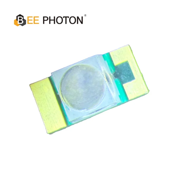
NIR LED E850-180-201L4
The E850-180-201L4 is a high-performance 850nm NIR LED engineered for precision industrial sensing. Manufactured by Bee Photon, this infrared emitter is designed to deliver high luminosity and exceptional stability, making it the ideal light source for demanding automation environments.
Swapping a Standard Emitter for a 4-Degree Rotary Encoder LED
Let’s talk about a real-world scenario. A manufacturer of industrial servo motors was having high-speed failure issues with their absolute encoders. They were using a standard 10-degree light source, and the motors were dropping counts at speeds above 3000 RPM.
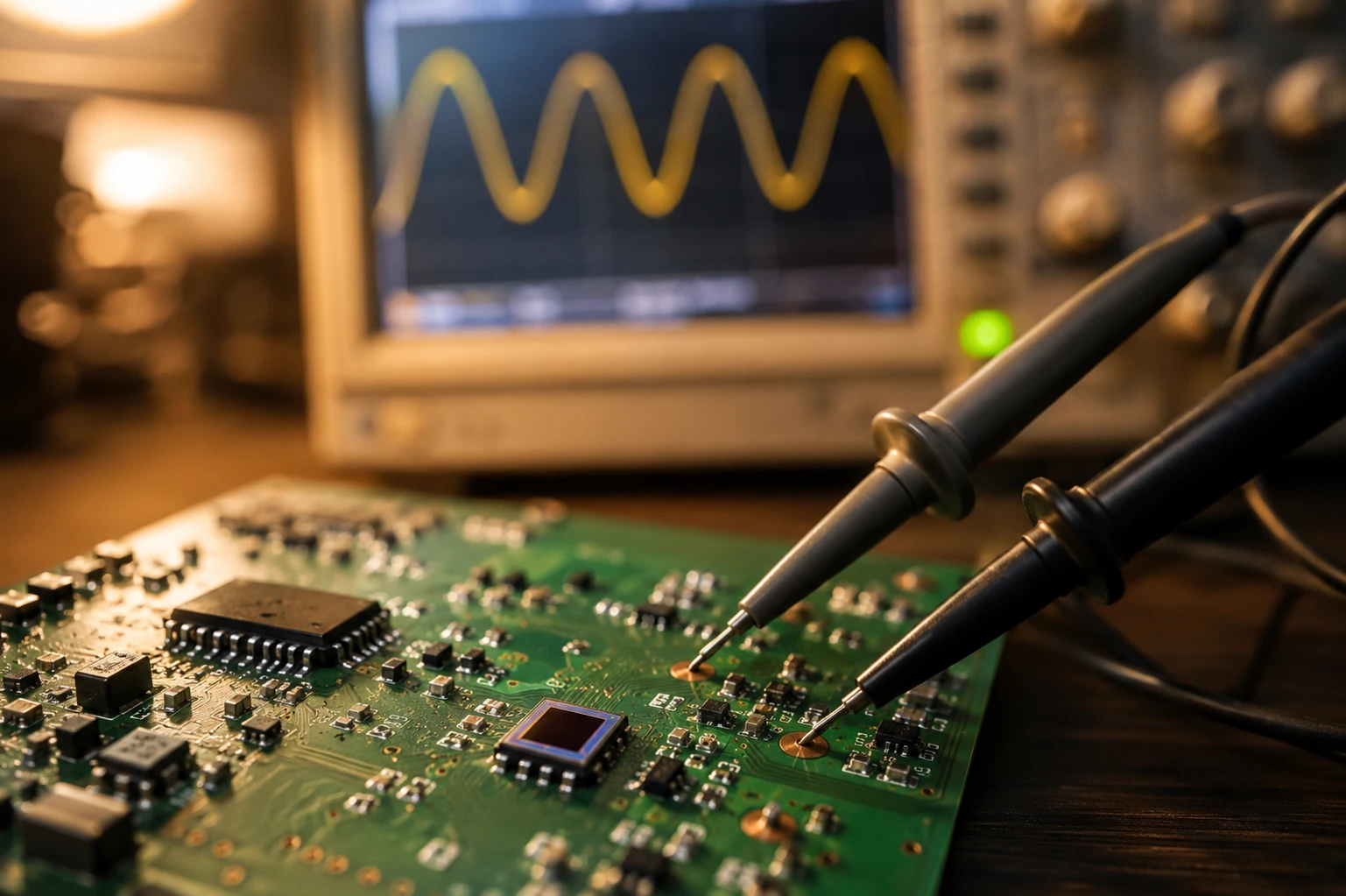
The engineering team analyzed the waveforms and realized that the analog sine/cosine signals were severely degraded. The wide beam was causing optical crosstalk across the tiny slits on the code disc.
The fix was straightforward. They swapped it for a 4-degree Rotary Encoder LED. Because the new light source kept the light highly collimated, the spot size on the photodetector shrank immediately.
This simple Rotary Encoder LED upgrade resolved the issue. The signal contrast ratio jumped from 52% to 91%, the random indexing errors vanished, and the motors were able to run up to 10,000 RPM without dropping a single count.
Sourcing a Premium Rotary Encoder LED
Sourcing a premium Rotary Encoder LED requires looking at specific parameters beyond just the beam angle. You need to make sure the light source is reliable, thermally stable, and matches your detector’s sensitivity.
Here is what to look for in a Rotary Encoder LED:
- Wavelength Matching: Most silicon photodiodes have their peak sensitivity in the near-infrared range, typically around 850nm to 870nm. Your Rotary Encoder LED wavelength must match this spectral band to maximize efficiency.
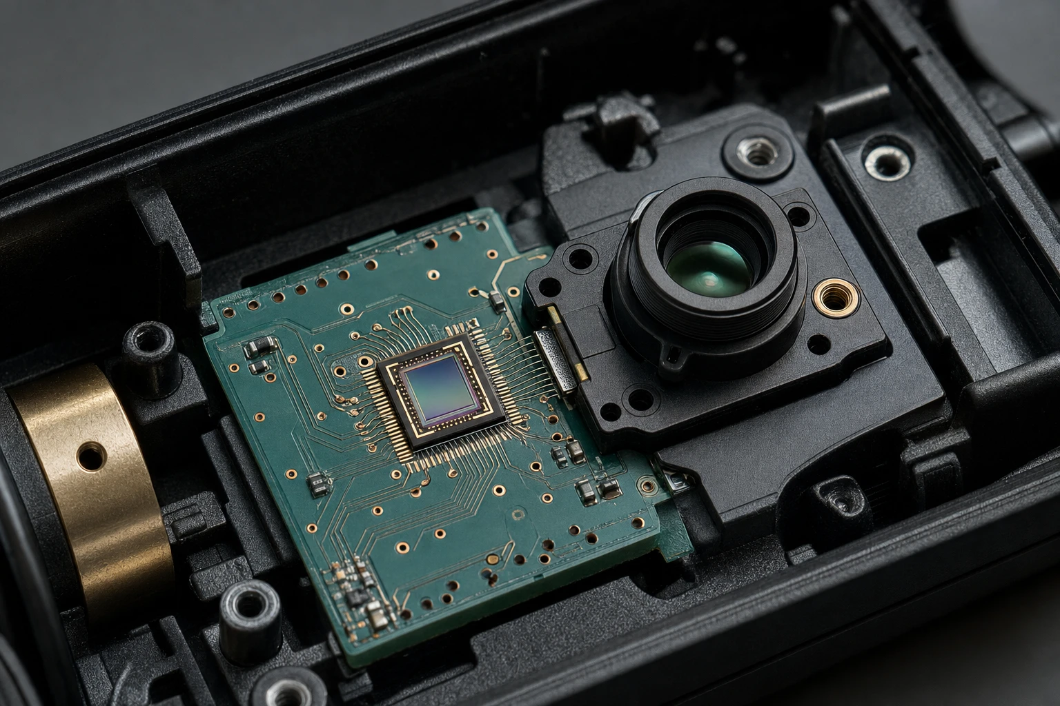
- Package Style: For tight encoder designs, surface-mount (SMD) packages are extremely popular. However, heavy-duty industrial encoders often use hermetically sealed metal cans with glass lenses to protect against moisture, dust, and thermal shock.
- Thermal Stability: Choose a Rotary Encoder LED with a low temperature coefficient of radiant power so your signal doesn’t fade when the motor gets hot.
If you want to ensure your sensors are highly reliable, checking out a reliable Rotary Encoder LED supplier is the best place to start. You can explore their extensive range of Rotary Encoder LED solutions by visiting the high-performance LED light sources catalog at BeePhoton. Selecting the right Rotary Encoder LED configuration will save you hours of calibration time during production and keep your machines running smoothly in the field.

Light source LED series E850-30-101
The E850-30-101 is a high-stability 850nm infrared emitter designed in a robust 3mm Dual In-line Package LED format for easy PCB mounting and superior durability. Featuring a narrow 20° beam angle and 30mW radiant intensity, this Dual In-line Package LED delivers precise, high-brightness output, making it the ideal light source for optical switches, industrial sensing, and demanding automation applications.
Frequently Asked Questions About Rotary Encoder LEDs
Why is a 4-degree Rotary Encoder LED superior to a 10-degree one?
A 4-degree Rotary Encoder LED keeps the light highly collimated. This means the light spot does not spread out as it travels from the emitter to the photodetector. This tight beam prevents optical crosstalk, increases signal contrast, and allows you to use much higher-resolution code wheels without signal degradation.
Can I use an indicator LED as a Rotary Encoder LED?
No, a standard LED is not a Rotary Encoder LED. Indicator LEDs have wide radiation patterns designed to be visible from various angles. They do not have the high-precision collimating lenses or tiny point-source chips required to create parallel light rays. Using one would result in a blurry shadow on your sensor and a failed encoder design.
How does temperature affect a Rotary Encoder LED?
The power of a Rotary Encoder LED can drop as the ambient temperature rises. Quality encoder-grade LEDs are designed with advanced semiconductor structures to minimize this thermal drift. This ensures that your sensor continues to read accurately even when industrial motors run hot.
Can a Rotary Encoder LED prevent mechanical alignment errors?
Using a narrow 4-degree Rotary Encoder LED allows for more mechanical breathing room. Because the beam stays parallel, small variations in the optical gap won’t cause the light spot to expand and blur. This makes your assembly process much more forgiving during manufacturing.
Optimize Your Optical Sensors Today
Are you tired of dealing with random indexing errors, weak signal contrast, or phase jitter in your optical encoder designs? If you want to push your system’s resolution limits, you cannot rely on generic, wide-angle light sources that flood your sensor with stray light.
A 4-degree beam angle is the sweet spot for optical rotary sensors. It provides the perfect balance of tight collimation, high on-axis intensity, and ease of mechanical alignment. If you need help finding the perfect Rotary Encoder LED for your project, our team of optical specialists is here to help.
At BeePhoton, we specialize in designing and manufacturing high-precision light sources and detector arrays tailored for demanding industrial applications. Investing in a high-quality Rotary Encoder LED means you get stable signals, higher resolution limits, and fewer field failures.
Ready to optimize your optical path? Visit the BeePhoton homepage to browse our technology, or contact BeePhoton directly to get a customized quote for your specific encoder design. You can also reach out to our engineering team directly via email at info@photo-detector.com. Let’s work together to make your motion sensors as accurate and reliable as possible!