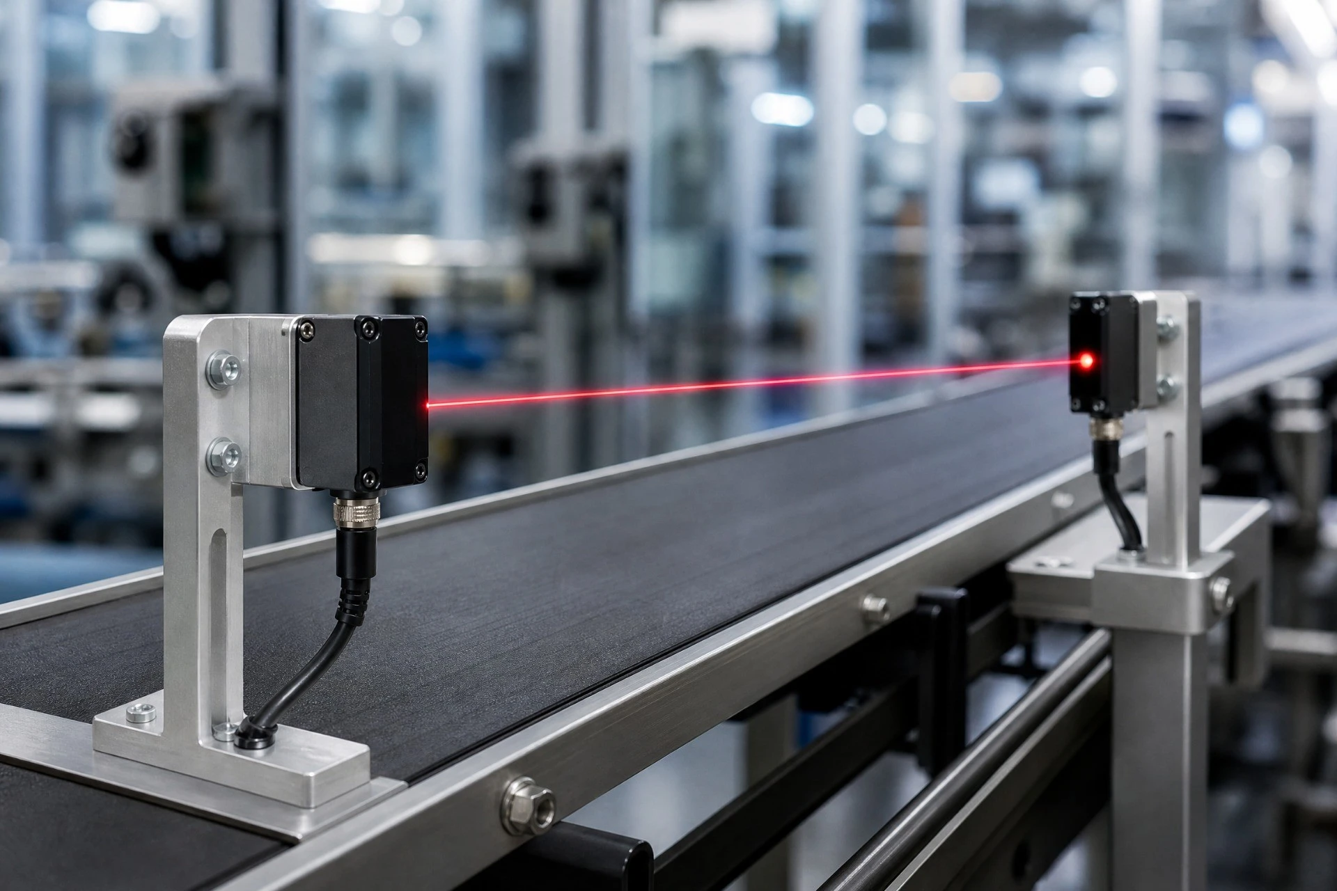
When you seal an industrial sensor inside a tight enclosure, you quickly realize that 625nm Red LED heat dissipation is going to be your absolute biggest hurdle. You spend weeks perfecting the optical path, designing a bulletproof IP67-rated enclosure, and choosing the perfect photodetector. You power up the prototype on your bench, and everything looks beautiful. But then, after a few hours of continuous operation inside a hot factory machine enclosure, your bright red beam starts looking like a dim, sad candle.
The culprit? You guessed it. You completely overlooked the physical realities of 625nm Red LED heat dissipation.
Red light-emitting diodes, particularly those operating around the 625nm dominant wavelength, are notoriously sensitive to thermal stress. Unlike their rugged blue and white cousins, red chips do not tolerate high temperatures. If you do not prioritize 625nm Red LED heat dissipation from day one, your sensor’s lifetime will plummet, and its optical output will suffer massive losses. In this guide, we will dive deep into the semiconductor physics of red LEDs, map out the mathematics of thermal transfer, and share a practical, real-world framework for keeping your sensors cool and reliable.
Why 625nm Red LED Heat Dissipation is Different
Unlike blue or white LEDs, red emitters require a completely different approach to 625nm Red LED heat dissipation. To understand why, we have to look closely at the semiconductor material itself. Most high-power blue, green, and white LEDs are fabricated using Indium Gallium Nitride (InGaN). InGaN is a highly resilient material system. Even when junction temperatures climb past 100 degrees Celsius, InGaN chips maintain a relatively stable optical output.
Red LEDs, on the other hand, are built using Aluminum Gallium Indium Phosphide (AlGaInP). This material behaves entirely differently. The physics of AlGaInP dictates that 625nm Red LED heat dissipation is a critical factor because of the relatively small bandgap offset between the active quantum wells and the cladding layers.
When the temperature of an AlGaInP chip rises, electrons that should be recombining to produce light actually get energized enough to escape from the active region of the quantum well. This carrier leakage is a massive thermal drain. Instead of converting electrical current into photons, the leaked electrons generate additional heat. This means that any design lacking proper 625nm Red LED heat dissipation will suffer from massive thermal droop. It is a vicious, self-reinforcing loop: poor 625nm Red LED heat dissipation leads to higher junction temperatures, which causes more carrier leakage, which in turn generates even more heat.
Furthermore, the material properties of AlGaInP make 625nm Red LED heat dissipation a moving target because of spectral shifts. For every 10 degrees Celsius increase in junction temperature, the peak emission wavelength shifts redder by about 1.3 to 1.5 nanometers. When your wavelength shifts from 625nm to 635nm, it’s a sign that your 625nm Red LED heat dissipation strategy has failed. This shift can render your sensor non-functional if your system relies on narrow optical bandpass filters to block ambient light. This means that failing to master 625nm Red LED heat dissipation can make your sensor stop working entirely, even if the LED is still glowing.
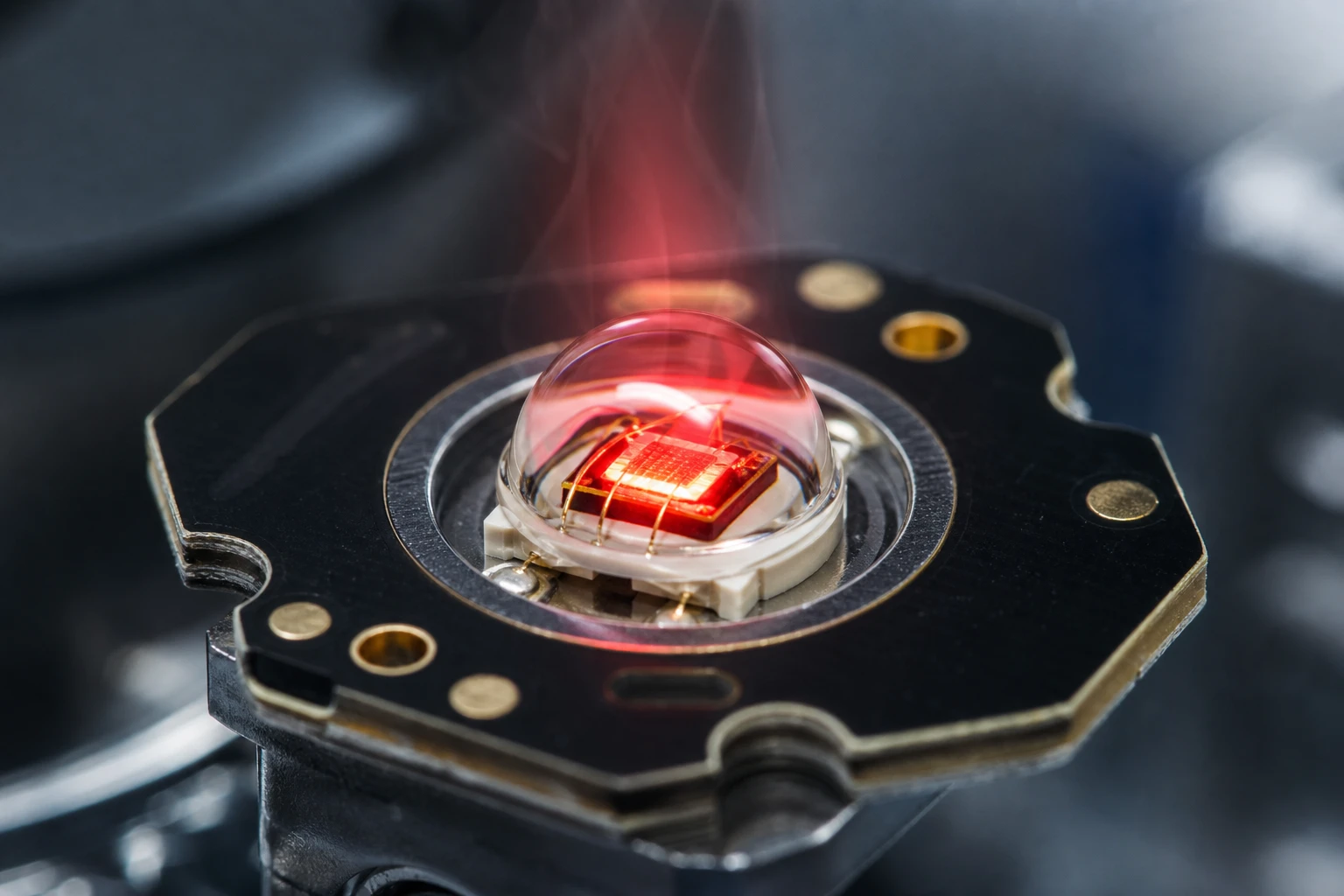
Red LED E628-10-201L4
High-Performance 625nm Red LED for Precision Optical Applications
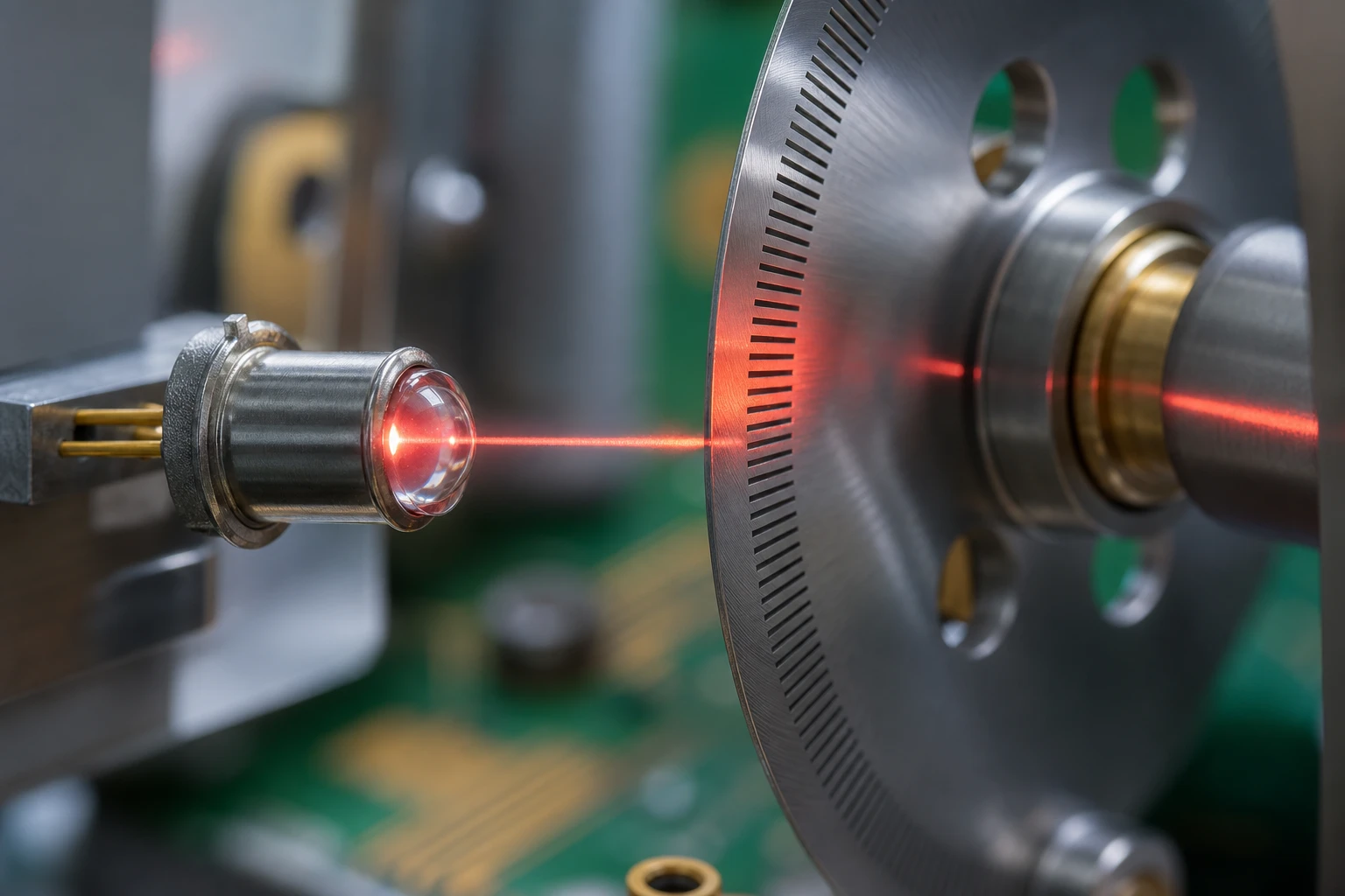
The E628-10-201L4 by Bee Photon is a premium 625nm Red LED designed to deliver high luminosity and exceptional reliability for demanding industrial applications. Engineered with a narrow 4-degree emission angle, this high-power red LED emitter provides focused light output, making it the perfect solution for precision optical sensing and signaling tasks where accuracy is paramount.
The Physics of AlGaInP and 625nm Red LED Heat Dissipation
In AlGaInP devices, the conduction band offset is small, which makes 625nm Red LED heat dissipation absolutely critical. This is why we focus heavily on 625nm Red LED heat dissipation to prevent carrier leakage from the active quantum wells. If you neglect 625nm Red LED heat dissipation, your electrical efficiency will tank, turning even more current into heat.
To predict how your system behaves, you must model 625nm Red LED heat dissipation using a basic thermal resistance network. This classic thermal formula is central to understanding 625nm Red LED heat dissipation constraints:
T_junction = T_ambient + P_dissipated * (R_thermal_junction_to_case + R_thermal_case_to_sink + R_thermal_sink_to_ambient)
Let’s break down each term of this formula so we can understand how it affects our design:
- T_junction (T_j): The actual temperature of the semiconductor die. For most high-quality red LEDs, this must stay below 125 degrees Celsius to prevent rapid degradation.
- T_ambient (T_a): The temperature of the air surrounding your sensor. In an air-conditioned office, this is 25 degrees Celsius. Inside a hot CNC machine room, it can easily reach 55 degrees Celsius.
- P_dissipated (P_d): The actual heat load in Watts. When evaluating 625nm Red LED heat dissipation, we must calculate the exact junction temperature of the AlGaInP die based on actual thermal loss, not just raw power.
- R_thermal_junction_to_case (R_th_j-c): The thermal resistance from the die to the thermal pad of the LED package. This is a fixed value provided by the manufacturer. For high-performance red LEDs, it is typically around 5 to 10 K/W.
- R_thermal_case_to_sink (R_th_c-s): The thermal resistance of your printed circuit board and thermal interface material (TIM). This is the area where you have the most design control.
- R_thermal_sink_to_ambient (R_th_s-a): The thermal resistance from your heatsink or enclosure to the outside air.
To calculate the actual heat load, this power calculation is the starting point of any realistic 625nm Red LED heat dissipation simulation:
P_dissipated = I_forward * V_forward * (1 - WPE)
Where WPE is the Wall-Plug Efficiency of the LED. For a high-luminosity 625nm red LED, the WPE is surprisingly low—often only around 20% to 25%. This means that 75% to 80% of the electrical power you pump into the LED is converted directly into heat. If you drive a red LED at 350mA with a forward voltage of 2.2V, your electrical input power is 0.77 Watts. With a WPE of 20%, your actual heat load is:
P_dissipated = 0.35 * 2.2 * (1 - 0.20) = 0.616 Watts
While 0.6 Watts might sound like nothing, in a tiny, sealed sensor housing with no active cooling, this heat will accumulate rapidly.
Solving 625nm Red LED Heat Dissipation in Sealed Enclosures
Industrial sensors are usually sealed, making 625nm Red LED heat dissipation incredibly tough due to the lack of airflow. You cannot use cooling fans or open ventilation slots. In these sealed environments, passive 625nm Red LED heat dissipation is your only real design option. If you don’t design a direct conductive path, your 625nm Red LED heat dissipation will rely on trapped air, which is a disaster.
Let’s walk through a realistic calculation of 625nm Red LED heat dissipation in an IP67 housing. Imagine an optical sensor mounted on a factory production line. The internal ambient temperature of the surrounding machinery is 50 degrees Celsius. The hardware designer, trying to save a few pennies, mounts a high-luminosity red LED on a standard two-layer FR4 board. The board is simply screwed into a plastic mounting bracket inside the plastic housing.
Without proper thermal planning, let’s look at how the thermal resistance network adds up:
- R_thermal_junction_to_case = 10 K/W
- R_thermal_case_to_sink (through FR4 to the air inside the housing) = 120 K/W
- R_thermal_sink_to_ambient (from the sealed plastic housing to the outside air) = 90 K/W
Let’s plug these values into our junction temperature formula:
T_junction = 50 + 0.616 * (10 + 120 + 90)T_junction = 50 + 0.616 * 220T_junction = 50 + 135.5 = 185.5 degrees Celsius
At 185.5 degrees Celsius, the AlGaInP material is way past its limits. The internal quantum wells will experience massive carrier leakage, reducing your light output by more than 70% in seconds. Within a few weeks of continuous operation, the epoxy package will turn yellow, and the LED will burn out. This is why neglecting the basic thermodynamic path is a fatal mistake for industrial sensor designs.
To fix this, you must bypass the air inside the housing and create a direct conductive path to the outer metal surface. If the housing is plastic, you need a metal insert or a dedicated thermal path. If the housing is aluminum, you should mount your PCB directly to the metal body. Doing this completely redefines your thermal performance, dropping the R_thermal_sink_to_ambient to under 20 K/W.
Substrate Material Choices for 625nm Red LED Heat Dissipation
The choice of board material is the single most important factor in 625nm Red LED heat dissipation. Standard FR4 is completely useless when it comes to 625nm Red LED heat dissipation at high currents. Its thermal conductivity is a miserable 0.25 W/mK. If you try to run high-current red LEDs on a standard FR4 board without modifications, you will destroy the device.
This comparison table shows how different board substrates handle 625nm Red LED heat dissipation pathways:
| Substrate Material | Thermal Conductivity (W/mK) | Typical Thermal Resistance (K/W) | Relative Cost | Recommendation for 625nm Red LED Heat Dissipation |
|---|---|---|---|---|
| Standard FR4 | 0.25 | 50 – 100 | Very Low | Avoid entirely for high-power red LEDs |
| FR4 with Thermal Vias | 3.0 – 10.0 | 15 – 30 | Low | Acceptable only for low-power or pulsed designs |
| Aluminum MCPCB | 1.0 – 3.0 | 5 – 10 | Medium | Excellent baseline for industrial sensors |
| Copper MCPCB | 400 (base) | 1 – 2 | High | Best performance for extremely tight, sealed spaces |
| Alumina Ceramic (Al2O3) | 24 – 30 | 2 – 4 | High | Outstanding reliability for harsh environments |
| Aluminum Nitride (AlN) | 170 – 200 | < 1 | Very High | Ultimate choice for high-power density arrays |
Upgrading to a metal core board is the easiest way to solve your 625nm Red LED heat dissipation bottlenecks. Shifting to an Aluminum Metal Core PCB (MCPCB) dramatically improves thermal flow by offering a path that is ten to fifty times more conductive than standard FR4.
We often use copper MCPCBs when we need maximum 625nm Red LED heat dissipation in the smallest possible footprint. Copper has a thermal conductivity of nearly 400 W/mK, allowing heat to spread laterally away from the tiny LED footprint much faster than aluminum. This rapid heat spreading is vital because it maximizes the effective area of your thermal interface material.
If you are looking to source pre-engineered or customized light source solutions that already incorporate these high-performance substrates, you can explore the high-performance industrial light source options in our product catalog. Choosing a pre-optimized module can save you months of thermal prototyping.
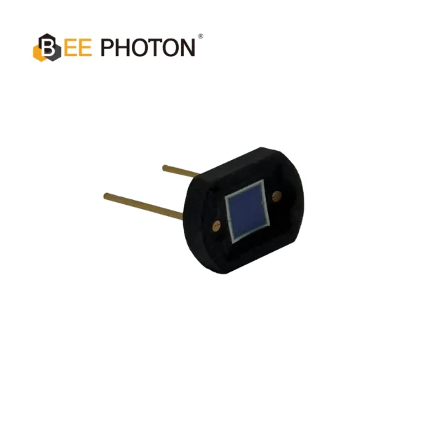
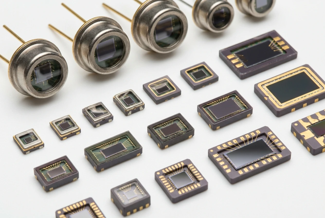
Si PIN Photodiode with low dark current (350-1060nm) PDCD07-001
Experience superior performance with our High Speed Si PIN Photodiode. Offering low dark current and a wide 350-1060nm spectral range, it ensures reliable and fast data transmission. This DIP-packaged high speed Si PIN Photodiode is your ideal choice for high-bandwidth optical communication systems.
The Impact of Thermal Interface Materials on 625nm Red LED Heat Dissipation
Selecting the right thermal paste or pad is crucial for successful 625nm Red LED heat dissipation. Even if you use a high-end copper MCPCB, your thermal path will suffer if you use a poor Thermal Interface Material (TIM). The microscopic surface roughness of metal surfaces means that when you press two metal plates together, only about 1% of the surface area is actually in contact. The rest is trapped air, which acts as a thermal barrier.
A cheap, thick thermal pad can completely ruin an otherwise great 625nm Red LED heat dissipation plan. To optimize 625nm Red LED heat dissipation, we aim for the thinnest possible layer of high-conductivity grease. Let’s look at the main options available:
- Thermal Grease (Silicone or Non-Silicone): This offers the thinnest possible bond line and excellent thermal conductivity (typically 3 to 8 W/mK). It is the absolute best choice for metal-to-metal interfaces but can be messy during high-volume assembly.
- Phase-Change Materials (PCM): These materials are solid at room temperature but melt and flow into microscopic gaps once the LED heats up. They offer performance comparable to thermal grease with much cleaner assembly, making them ideal for high-volume production.
- Thermal Pads: These are thick, squishy pads. While they are very easy to install, they have relatively high thermal resistance. Only use them if you must bridge a wide mechanical gap.
When designing your mechanical stack-up, always ensure there is adequate mounting pressure. Without enough pressure, the TIM cannot displace the trapped air, rendering your thermal calculations completely useless in practice.
Optical Consequences of Inadequate 625nm Red LED Heat Dissipation
What happens to your sensor’s performance if you ignore 625nm Red LED heat dissipation? As temperature rises, poor 625nm Red LED heat dissipation causes the optical signal to degrade. This is where most engineers get caught off guard. You might design a system where the thermal path is just good enough to keep the LED from burning out, but you forget that the optical receiver is expecting a very specific wavelength.
As junction temperature increases, the energy bandgap of the AlGaInP material shrinks. This bandgap narrowing causes a pronounced shift in the emission spectrum. Let’s write down the wavelength shift formula:
Wavelength_Shift = T_coefficient * (T_junction - 25)
For a typical AlGaInP red LED, the temperature coefficient is approximately 0.14 nanometers per degree Celsius. If your junction temperature rises from 25 degrees Celsius to 105 degrees Celsius, the math shows:
Wavelength_Shift = 0.14 * (105 - 25) = 11.2 nanometers
Your 625nm LED is now emitting light at 636.2nm.
In high-performance industrial photoelectric sensors, designers place narrow bandpass filters over the receiver to block out ambient factory lighting and high-frequency noise. If your optical filter is centered at 625nm with a bandpass of +/- 5nm, your shifted 636.2nm light will be completely blocked by the filter. The sensor will report a failure, even though the LED is physically turned on and glowing. This makes 625nm Red LED heat dissipation an optical issue, not just a thermal reliability concern.
Additionally, hot AlGaInP chips suffer from a severe drop in relative light output. At a junction temperature of 100 degrees Celsius, a red LED only produces about 60% of the light output it does at room temperature. If you do not prioritize thermal management, your sensor’s operating range will shrink dramatically as the system warms up.
How We Validate 625nm Red LED Heat Dissipation in the Lab
I’ll be brutally honest here: most high-end 3D thermal simulation software packages are a massive waste of time for 90% of basic sensor designs. Academics love them because they generate beautiful color charts, but in the real world, a simple spreadsheet with a 1D thermal resistance network will get you within 5% of the actual temperature in about ten minutes. Instead of spending three days setting up complex mesh boundaries in FEA software, you can build a physical prototype and measure it directly.
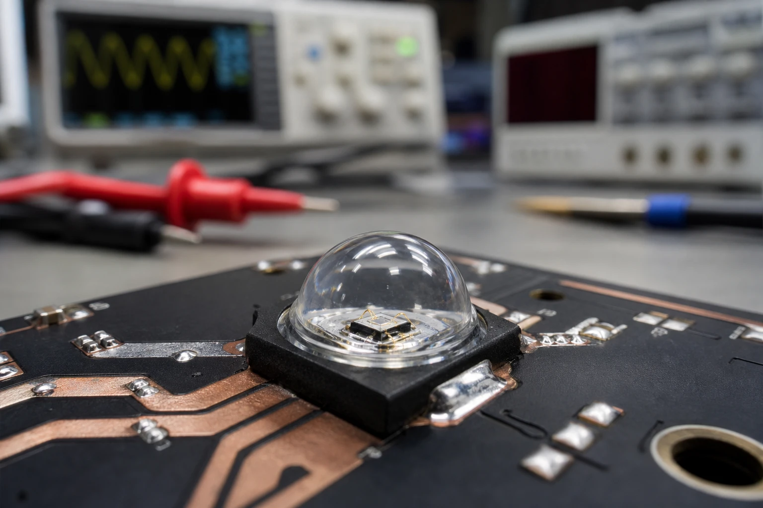
But how do you measure junction temperature? You cannot verify 625nm Red LED heat dissipation simply by looking at the outside of your sensor with an IR camera. The silicone lens of the LED blocks infrared radiation, and the thermal camera only measures the outer surface temperature, not the internal semiconductor junction.
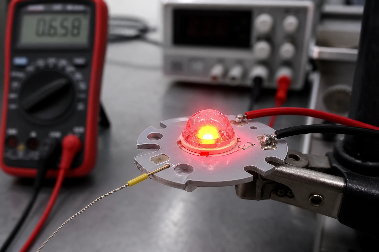
We use the transient forward voltage method to get a true reading of 625nm Red LED heat dissipation. The forward voltage of a semiconductor diode drops linearly as temperature increases. By measuring this small voltage drop, we can use the LED itself as a highly precise internal thermometer.
This laboratory process gives us real, physical data on our 625nm Red LED heat dissipation performance:
- Calibration: We place the unpowered sensor inside a highly accurate temperature-controlled oven. We apply a tiny, non-heating current pulse (typically 1mA) to measure the forward voltage at 25, 50, 75, and 100 degrees Celsius. This gives us a highly accurate Calibration Curve (typically around -2 mV/°C).
- Thermal Equilibrium Test: We bring the sensor out of the oven, power it up at its full operating current (e.g., 350mA) inside its sealed housing, and let it run until the temperature completely stabilizes.
- Measurement: We rapidly switch the current from the high operating current back to the 1mA sensing pulse and record the hot forward voltage.
- Analysis: Using our calibration curve, we translate this hot voltage back into an exact junction temperature.
We used this exact method to solve a client’s chronic 625nm Red LED heat dissipation failures in a hot automotive factory. Their safety light curtains were constantly failing on hot summer days. The original designer had mounted a high-power red LED on a cheap FR4 board with absolutely no thermal coupling to the outer aluminum bracket.
Our team at BeePhoton stepped in. We redesigned the internal PCB using an Aluminum MCPCB, selected one of our optimized, thermally rugged light sources, and specified a high-performance phase-change TIM. When we tested the new prototype using the forward voltage method, the junction-to-ambient thermal resistance had dropped from a massive 125 K/W down to just 22 K/W. The peak wavelength shift was cut to less than 2nm, completely eliminating their sensor drop-out issues.
Engineering Checklist for 625nm Red LED Heat Dissipation
Here is a quick reference guide to help you optimize 625nm Red LED heat dissipation on your next project:
- Avoid standard FR4: If your operating current is over 100mA, use an Aluminum MCPCB as your starting baseline.
- Maximize copper thickness: Specify 2 oz copper instead of standard 1 oz copper. Thicker copper layers help spread heat laterally, which is crucial for efficient heat transfer.
- Design a direct metal path: If you are using a metal enclosure, make sure your MCPCB has direct contact with the metal housing. Do not let air act as an insulator.
- Choose the right TIM: Use a thin layer of high-conductivity thermal grease or a phase-change material rather than thick, lazy thermal pads.
- Calculate thermal drift: Do the math on wavelength shift and make sure your optical receiver’s bandpass filter is wide enough to handle the drift.
- Keep thermal paths short: The shorter the physical distance from the LED thermal pad to the outside of the housing, the better your thermal efficiency will be.
- Test with the V_f method: Do not rely on thermal cameras or basic simulations alone. Use the transient forward voltage method to verify your actual junction temperature.
Always prioritize conduction over convection when dealing with 625nm Red LED heat dissipation. Air is a terrible thermal conductor; you must design a direct, solid conduction path to the outside world.
We hope this guide on 625nm Red LED heat dissipation helps you with your next hardware project. Designing reliable optoelectronic systems requires a deep understanding of thermal management.

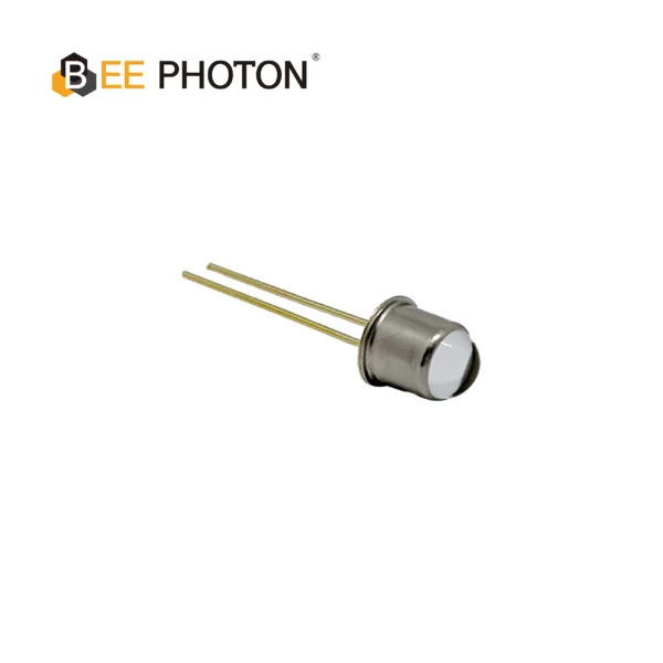
Light source LED series E660-10-001
Our plastic packaged LED in an SMD format ensures high uniformity for automated assembly. This resin-molded LED offers high reliability for various industrial applications.
Let’s Solve Your Thermal Challenges Together
Are you tired of seeing your optical sensors lose range and reliability when things get hot on the factory floor? Dealing with carrier leakage, spectral drift, and thermal degradation can be incredibly frustrating.
At BeePhoton, we design our optoelectronic products with a focus on robust 625nm Red LED heat dissipation. Our engineering team has decades of experience designing high-performance light sources and optical detectors that stand up to the most demanding industrial applications. Whether you need a customized Aluminum MCPCB layout, thermal simulation support, or high-performance components, we can help you optimize your next design.
To explore how we build high-reliability components, check out our BeePhoton homepage. You can also browse our specialized high-performance industrial light source options to find the perfect starting point for your next design. If you need customized advice on 625nm Red LED heat dissipation, please reach out. You can reach out to our optical engineering team directly to submit a drawing, ask a technical question, or request a custom thermal management quote. Our engineers specialize in optimizing 625nm Red LED heat dissipation for high-reliability applications, and we would love to help you build a cooler, tougher product.
FAQ: Common Questions on 625nm Red LED Heat Dissipation
How does ambient temperature affect 625nm Red LED heat dissipation?
Ambient temperature acts as the baseline for your thermal system. Because thermal transfer depends entirely on the temperature difference between the LED junction and the outside air, a high ambient temperature reduces the rate of heat transfer, which is why ambient temperature directly impacts your 625nm Red LED heat dissipation efficiency. If the ambient temperature inside a factory rises by 20 degrees Celsius, your LED junction temperature will rise by exactly 20 degrees Celsius as well, unless you actively improve your thermal pathway.
Can thermal vias on FR4 handle 625nm Red LED heat dissipation?
Yes, you can use thermal vias on a standard FR4 board, but they are usually not enough for high-current 625nm Red LED heat dissipation. While drilling vias and filling them with copper or solder helps carry heat to the backside of the board, the overall thermal conductivity of FR4 is still very poor. If you are driving your red LEDs at 350mA or higher, an aluminum MCPCB is a much safer, more reliable choice to protect the semiconductor junction.
What is the maximum junction temperature for safe 625nm Red LED heat dissipation?
For most high-luminosity AlGaInP red LEDs, the absolute maximum rated junction temperature is 125 to 150 degrees Celsius. However, to ensure safe, long-term 625nm Red LED heat dissipation and avoid rapid degradation, you should design for a safety margin and keep your target junction temperature below 90 to 100 degrees Celsius under worst-case operating conditions. Every 10 degrees Celsius drop in junction temperature roughly doubles the operating life of your LED.