If you’ve ever sat there staring at a datasheet wondering how the heck you’re supposed to figure out what current your photodiode will actually spit out, you’re not alone. I’ve been helping engineers with this exact problem for years at BeePhoton, and the truth is most online tutorials either stay way too theoretical or skip the messy real-world bits.
Today I’m walking you through exactly how to calculate photodiode current in a way that you can actually use when you’re doing circuit simulation or picking resistors. No fluff, just the stuff that works.
Why This Actually Matters in Real Designs
Most engineers I talk to care about one thing: will my circuit behave the way I expect when light hits the detector? Getting the output current wrong by even 20-30% can completely throw off your gain calculations, mess up your SNR, or force you to redo your PCB.
I’ve seen designs where people used the peak responsivity number from the datasheet and then got surprised when their actual current was half of what they calculated. That’s exactly what we’re going to avoid.
The Basic Formula You Need to Know
The core equation for calculating photodiode current is actually pretty simple:
I_ph = R × P
Where:
- I_ph = photocurrent (what you’re trying to find)
- R = responsivity of the photodiode (in A/W)
- P = incident optical power (in Watts)
That’s the responsivity formula in its most basic form. But like most things in engineering, the devil is in the details.
Understanding Responsivity – It’s Not a Constant
Here’s something a lot of people get wrong: responsivity changes with wavelength. A silicon PIN photodiode that gives you 0.6 A/W at 900 nm might only give you 0.1 A/W at 400 nm.
I always tell people to treat the responsivity curve as your best friend. Don’t just grab the highest number on the datasheet.
Let me show you a typical responsivity table for our Si PIN photodiodes:
| Wavelength (nm) | Typical Responsivity (A/W) |
|---|---|
| 400 | 0.12 |
| 650 | 0.38 |
| 850 | 0.58 |
| 950 | 0.62 |
| 1050 | 0.35 |
If you’re working with 850 nm VCSELs, you’d use something around 0.58 A/W. But if your light source is 405 nm, you’re looking at a completely different ballgame.

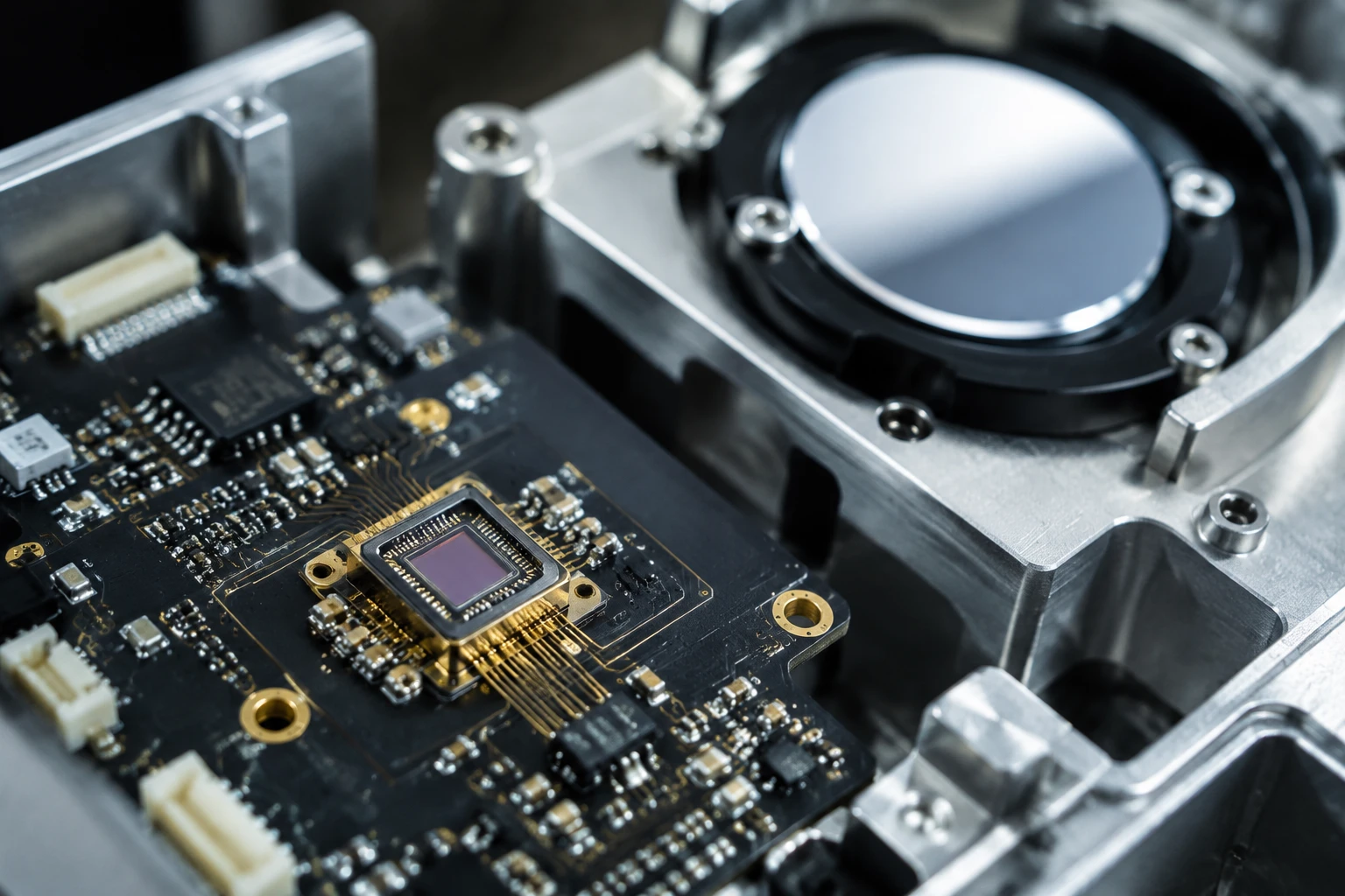
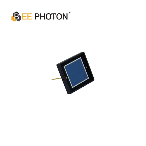
Si PIN Photodiode with low dark current (350-1060nm) PDCC14-001
Our Si PIN for precision photometry delivers exceptional accuracy for sensitive light measurement. With low dark current, this photodiode is ideal for analytical and scientific instruments requiring precise results.
Step-by-Step: How to Calculate Photodiode Current
Let’s do this with a real example I worked on last month.
Scenario: Engineer needed to know the expected current from a 1 mm² Si PIN photodiode receiving 50 µW of 850 nm light.
Step 1: Find the right responsivity
From the curve (or table above), at 850 nm we use R = 0.58 A/W
Step 2: Convert power to Watts
50 µW = 50 × 10^-6 W = 5e-5 W
Step 3: Plug into the formula
I_ph = 0.58 A/W × 5e-5 W = 0.000029 A = 29 µA
Pretty straightforward, right? But here’s where it gets interesting.
Don’t Forget These Real-World Factors
1. Quantum Efficiency
Sometimes you’ll see the responsivity formula written as:
R = (η × q × λ) / (h × c)
Where:
- η = quantum efficiency
- q = electron charge (1.6 × 10^-19 C)
- λ = wavelength in meters
- h = Planck’s constant (6.626 × 10^-34)
- c = speed of light (3 × 10^8 m/s)
I usually don’t calculate from scratch unless I’m doing something exotic. Most of the time the manufacturer already gives you the measured responsivity, which is way more accurate.
2. Temperature Effects
Responsivity shifts with temperature. For silicon, you can expect roughly 0.1-0.2% change per °C. In a harsh environment, this can actually matter more than you think.
3. Surface Reflection and Packaging
The numbers on the datasheet usually assume the light actually reaches the active area. If you have a window, epoxy, or any optical interface, you’re going to lose some light. I’ve seen 8-12% losses just from Fresnel reflection.
Calculating Load Resistor Values
This is where most engineers actually need the current number – to figure out their transimpedance amplifier or simple load resistor.
Let’s say you want 1V output for 50 µW of light (from our earlier example where we got 29 µA).
R_load = V_desired / I_ph = 1V / 29e-6A ≈ 34.5 kΩ
I usually recommend starting with the nearest standard value (33k or 36k) and then adjusting based on actual measurement. Simulation is great, but photodiodes in real life often have surprises.
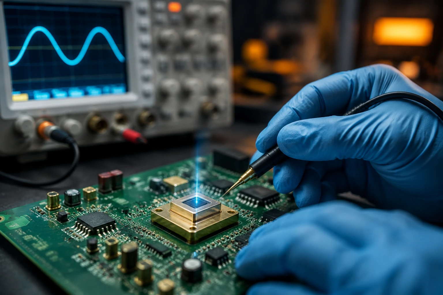
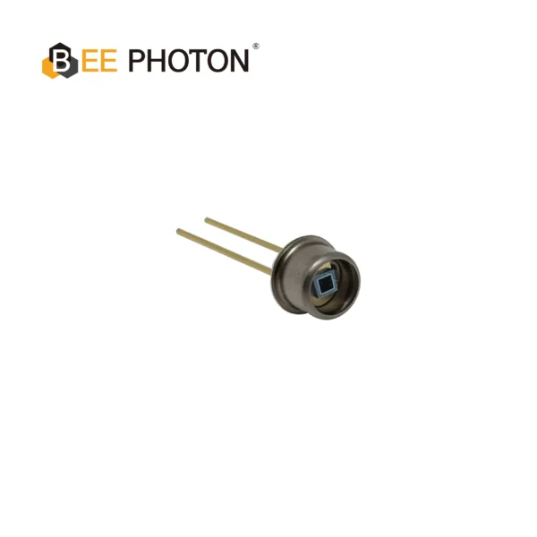
Si PIN Photodiode with low dark current (350-1060nm) PDCD100-101
Upgrade your devices with our Si PIN Photodiode for Optical Measurement. It delivers high accuracy across a 350-1060nm range with minimal dark current. Ideal for various industrial sensing and measurement applications, this high-performance sensor guarantees precision and repeatability.
Quick Comparison Table: Different Photodiode Types
| Photodiode Type | Typical Responsivity @850nm | Dark Current | Speed | Best For |
|---|---|---|---|---|
| Si PIN | 0.55–0.62 A/W | Very low | Fast | General purpose |
| Si APD | 20–80 A/W (with gain) | Higher | Fast | Low light |
| InGaAs | 0.9–1.0 A/W | Low | Very Fast | 1310/1550nm |
If you’re working in the visible to near-IR range, our Si PIN photodiodes usually give you the best combination of low dark current and decent speed.
A Real Project That Went Sideways (And What We Learned)
Last year a customer came to us after their simulation showed 45 µA but their prototype was only producing 18 µA. Turns out they had used the responsivity value at the wrong wavelength and completely missed the 4 dB optical loss from their fiber coupling.
After recalculating using the actual measured optical power at the detector surface, everything matched up. The fix was embarrassingly simple once we looked at the real numbers.
This is exactly why I always tell people: measure what you can, calculate what you must, and never trust simulation alone.
Advanced Tips for More Accurate Calculations
- Always derate your optical power by at least 20% for aging and temperature effects
- Consider the photodiode’s active area versus your beam size (spatial uniformity matters)
- For pulsed applications, think in terms of energy per pulse rather than average power
- When doing Monte Carlo simulations, make responsivity one of your variables with ±8% spread
Common Mistakes I Still See in 2025
- Using the “typical” responsivity from the top of the datasheet without checking the curve
- Forgetting to convert units (mixing mW and µW is surprisingly common)
- Assuming all the light hits the active area
- Ignoring bandwidth limitations when calculating maximum usable current
Ready to Get Serious About Your Photodiode Circuit?
Look, you can keep guessing or you can actually calculate this stuff properly. Most of the time the difference between “works okay” and “works perfectly” comes down to doing these calculations right.
If you’re currently designing a circuit and want a second pair of eyes on your photodiode current calculations, we’re happy to help. Drop us a message through our contact page or shoot an email to info@photo-detector.com. Sometimes a 10-minute conversation saves weeks of debugging.
We regularly help engineers pick the right Si PIN photodiodes and get the calculations spot-on before they even order parts.
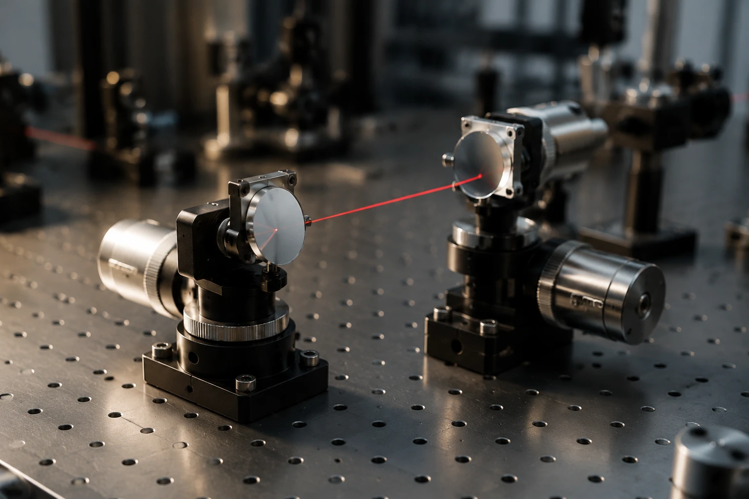
Si PIN Photodiode with UV sensitivity enchanced (190-1100nm) PDCT01-F01
Experience precise UV detection with our Quartz Window Si PIN Photodiode. Ideal for spectroscopy, it offers high sensitivity and low noise across 190-1100nm. This reliable Si PIN photodiode ensures accurate analytical results.
FAQ
What is the formula to calculate photodiode current?
The basic formula is I_ph = Responsivity × Optical Power. Just make sure you’re using the responsivity value that matches your actual wavelength.
Does temperature affect how I calculate photodiode current?
Yes. Responsivity typically changes by about 0.1-0.2%/°C in silicon photodiodes. For precision work, you should either control temperature or compensate for it in your calculations.
How do I choose the right load resistor after calculating photodiode current?
Take the voltage you want to see and divide it by your calculated photocurrent. Then pick the closest standard resistor value and verify with real measurements. Simulation gets you close, but reality always has the final say.