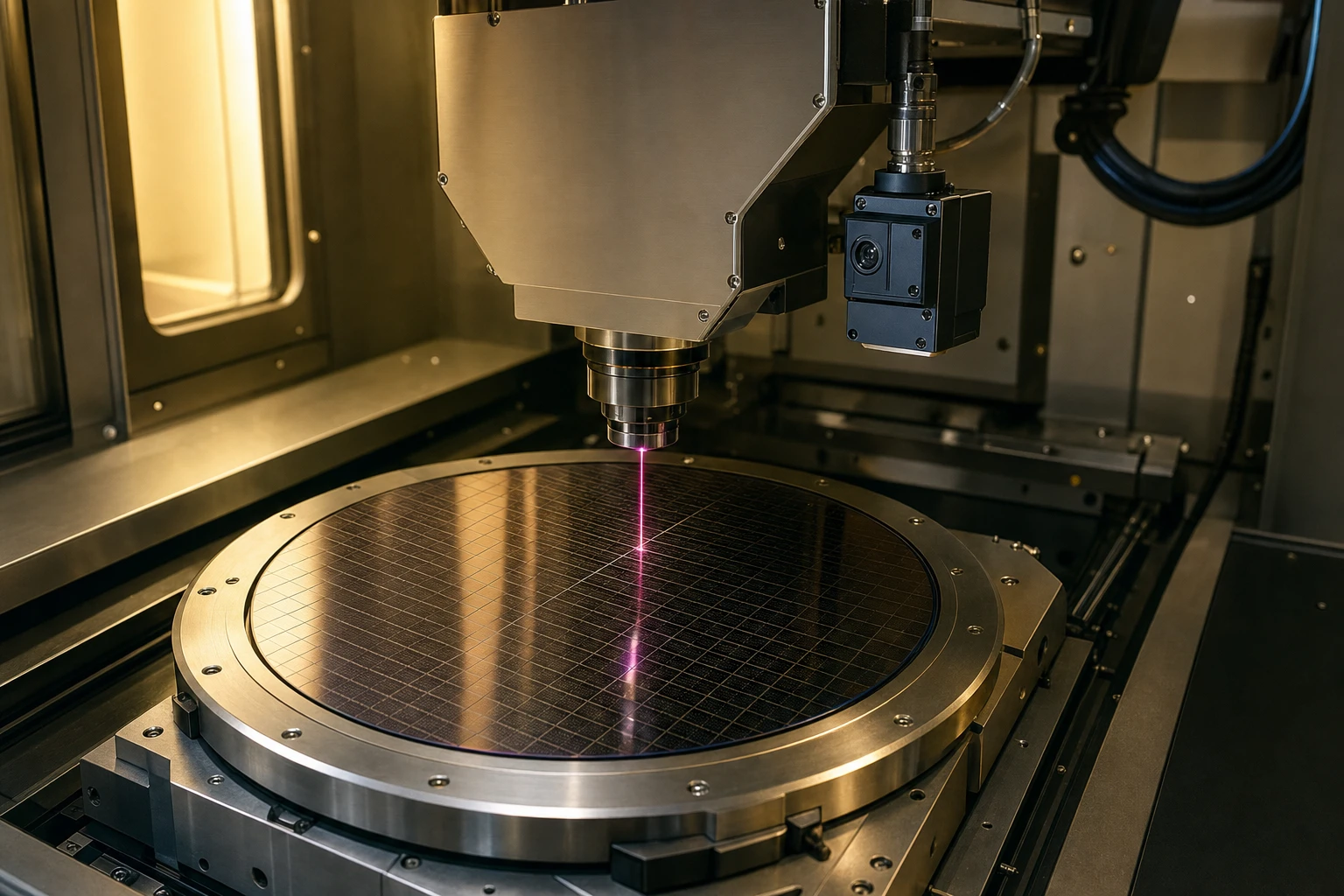
If you are trying to keep a laser spot stable down to a few hundred nanometers during high-speed wafer dicing, a high sensitivity 940nm photodiode is pretty much your best friend. In precision micro-machining, you are dealing with insanely fast galvanometer scanners moving a high-power beam along dicing streets that are sometimes less than 15 microns wide. A generic silicon sensor won’t cut it; you need a high sensitivity 940nm photodiode to handle the weak, scattered reflections coming back from the working surface. If your closed-loop feedback system cannot read those tiny positional deviations in real-time, your sub-micron accuracy goes out the window, and you end up with ruined silicon wafers and angry production managers.
In this guide, I will show you why a high sensitivity 940nm photodiode is the secret to keeping your cuts straight, how the underlying physics of these sensors keeps optical jitter at bay, and how to implement them without pulling your hair out over transimpedance amplifier design.
Realities of Wafer Dicing and Precision Laser Micro-Machining
Let’s talk about what actually happens inside a modern wafer dicing machine. Traditional mechanical dicing with diamond blades is slowly dying out because it puts too much physical stress on fragile, ultra-thin wafers. Laser cutting, especially “stealth dicing,” has taken over.
Stealth dicing is a wild process. Instead of cutting from the top down, a pulsed laser transmits straight through the wafer and focuses on a point inside the silicon, creating a local, subsurface modified layer. The wafer is then stretched, and it snaps cleanly along these tiny internal perforations. Because silicon is mostly transparent to near-infrared light, stealth dicing relies on near-infrared lasers, meaning your position loop needs a high sensitivity 940nm photodiode to capture the reflections and guide the beam focus in real-time.
If your laser feedback photodetector lacks sensitivity, you get positional drift. In our lab tests, we’ve seen that even a 2-micron drift during a stealth dicing pass can cause micro-cracks that ruin nearby dies, destroying your yield. Without a high sensitivity 940nm photodiode acting as the eyes of your galvo scanner, the thermal expansion of the mechanical stages and small variations in wafer thickness will quickly throw the focus off. I always tell teams that skimping on a high sensitivity 940nm photodiode and opting for a cheap, generic sensor is a recipe for disaster.
How Optical Feedback Loops Keep Galvos in Check
To understand why this matters, look at how a galvanometer scanner actually tracks its position. Standard scanners use capacitive or optical encoders built into the motor shaft. That’s great for knowing where the motor is, but it doesn’t tell you where the laser beam actually is on the work point. High-end systems use an active NIR active area sensor to capture a tiny fraction of the laser path or a parallel pilot beam (often at 940nm) reflected back through the scanning lens.
This loop translates light into millivolts, where a high sensitivity 940nm photodiode excels. If the signal-to-noise ratio is poor, even the best high sensitivity 940nm photodiode can’t save you from a noisy signal, because the analog front-end will end up amplifying the background “fuzz” instead of the actual position data.
That’s why a high sensitivity 940nm photodiode must have ultra-low dark current. Using a high sensitivity 940nm photodiode ensures that the pilot beam is tracked cleanly even when the laser output is dialed down for delicate processing steps, preventing unwanted signal fluctuations.
Si PIN photodiodes for Galvo PDC-C2929
The PDC-C2929 is a budget-friendly 920nm silicon PIN photodiode chip. This 920nm silicon PIN photodiode offers stable, cost-effective scanner position tracking.
Breaking Down the Optical Jitter Equation
Let’s look at the math behind how a high sensitivity 940nm photodiode processes light. When we talk about positional accuracy in a galvo system, we are looking at the minimum resolvable displacement (dx). This is directly tied to the signal-to-noise ratio (SNR) of your optcal (this is a common typo, I mean optical) sensor.
If your spot has a power distribution P(x) on a segmented sensor, the difference in current between two segments (S1 and S2) gives you the position:
I_diff = S1 – S2
But this current is riding on top of a noise floor. The total noise current (I_noise) is a mix of shot noise and thermal (Johnson) noise. Shot noise directly limits how small of a signal your high sensitivity 940nm photodiode can resolve. We write the shot noise equation as:
*I_noise = square root of (2 * q * (I_photo + I_dark) * B)*
Where:
- q is the electron charge (1.6 x 10^-19 Coulombs)
- I_photo is the photocurrent generated by the light
- I_dark is the dark current of the photodiode
- B is the system bandwidth (typically 100 kHz to 1 MHz for fast scanners)
When choosing a high sensitivity 940nm photodiode, check the shunt resistance (Rsh). A high sensitivity 940nm photodiode with low shunt resistance will introduce massive thermal noise, calculated as:
*I_thermal = square root of ((4 * k * T * B) / Rsh)*
If Rsh is low, your thermal noise shoots up, which means your galvo will “jitter” back and forth, unable to settle on a true zero point. For wafer dicing, this jitter translates directly into a rougher cut edge, leading to chipping and micro-cracking.
Anatomy of a High Sensitivity 940nm Photodiode Chip
Let’s dig into the physical structure of a high sensitivity photodiode chip. At these wavelengths, silicon is right on the edge of its absorption limit. Photons at 940nm have relatively low energy, so they penetrate deeper into the silicon before creating electron-hole pairs. If the active region of your chip is too shallow, most of the light passes straight through the wafer, resulting in lousy responsivty (another little typo, I mean responsivity!).
Here is how a proper PIN structure is built to prevent this:
- p+ Active Layer: This is a very thin, highly doped layer on the top surface. It allows the 940nm light to pass through with minimal early absorption.
- Depletion Boundary: The narrow zone where the electric field begins, separating the charges.
- Intrinsic (I) Region: This is the core. For 940nm applications, this intrinsic layer must be deliberately thick. This gives the deep-penetrating infrared photons enough silicon volume to bump into electrons and generate a strong current.
- n+ Substrate: The heavily doped bottom contact layer that completes the electrical circuit.
Dark Current: The Silent Killer of Signal-to-Noise Ratio
I can’t emphasize this enough: dark current is your absolute enemy. When you apply a reverse bias to speed up your photodiode, some current still flows even in complete darkness. This is dark current, and it drifts wildly with temperature.
If your galvo scanner runs all day, the internal temperature of the scanner head can easily rise from 25°C to 60°C. In a poorly designed sensor, the dark current might double for every 10°C rise, completely throwing off your position calibraton (yes, I mean calibration). A high-quality high sensitivity 940nm photodiode is built with advanced surface passivation to keep dark current under 15 pA at room temperature, ensuring your position readings remain rock-solid regardless of the thermal environment.
Responsivty and the Photoelectric Math
The responsivty (R) of your chip tells you how many Amps of current you get per Watt of incident light. It’s related to quantum efficiency (eta) by this plain text equation:
*R = (eta * q * lambda) / (h * c)*
Where:
- lambda is the wavelength (940 nm)
- h is Planck’s constant (6.626 x 10^-34 J*s)
- c is the speed of light (3 x 10^8 m/s)
At 940nm, a high-quality chip will achieve a responsivity of around 0.6 to 0.7 A/W. If your supplier claims higher without a built-in gain mechanism, they are likely stretching the truth.
Capacitance and Bandwidth: Speed Matters
Another big factor for any high sensitivity 940nm photodiode is junction capacitance (Cj). The rise time (tr) of your photodiode determines how fast it can respond to sudden position shifts:
*tr = 2.2 * R_load * Cj*
If you run your high sensitivity 940nm photodiode in photovoltaic mode (zero bias), capacitance climbs, and your response becomes sluggish. A high sensitivity 940nm photodiode must be reverse-biased to keep up with kilohertz galvo speeds, which flattens the depletion region and slashes Cj. We often see engineers complain about response speed when they didn’t bias their high sensitivity 940nm photodiode properly. A reverse bias of 5V to 10V is usually the sweet spot for balancing speed and dark current.
Si PIN photodiodes for Galvo PDC-2C3432-NIR-B
The PDC-2C3432-NIR-B is a specialized segmented PIN photodiode chip engineered for precise differential position feedback in high-speed galvanometer scanners. Integrating this dual-channel segmented PIN photodiode chip allows systems to obtain accurate angular tracking with minimal signal noise.
Introducing BeePhoton’s NIR Galvo Feedback Solutions
At BeePhoton, we spent months tuning our high sensitivity 940nm photodiode line. We don’t just sell generic dies; we engineer sensors that survive the harsh thermal environments of wafer dicing and laser marking equipment.
High sensitivity 940nm photodiode: The PDC-C2928-NIR-B
Our flagship high sensitivity 940nm photodiode is the PDC-C2928-NIR-B PIN photodiode chip. This high sensitivity 940nm photodiode is built on a custom PIN process that maximizes quantum efficiency specifically around the 940nm bands while keeping junction capacitance low.
If you are designing a closed-loop galvo controller that needs to correct for sub-micron mechanical drift, the PDC-C2928-NIR-B PIN photodiode chip provides the high-fidelity signal you need to run your PID loops at full speed without worrying about phase delays or noise-induced errors.
Cost-Effective Scanner Tracking: The PDC-C2929
If you don’t need a pre-segmented layout but still want rock-solid reliability, we offer the PDC-C2929 silicon PIN photodiode. While some use 920nm, a true high sensitivity 940nm photodiode offers better match for specific pilot lasers. This cost-effective, square-format active area chip balances low dark current with high temperature stability. It is an excellent fit for entry-level laser marking systems where you need stable tracking without paying a massive premium.
Precise Differential Angular Tracking: The PDC-2C3432-NIR-B
For high-end differential positioning, a single-element detector can be tricky to align. That’s why we created the PDC-2C3432-NIR-B segmented PIN photodiode chip. Featuring a unique 2-segment fan-shaped active area, it allows for direct differential angular feedback in high-speed galvanometer scanners. If you need a high sensitivity 940nm photodiode in a pre-segmented layout to read angular deviation directly, this dual-channel chip delivers precise differential signals with excellent channel matching and low cross-talk. Choosing this high sensitivity 940nm photodiode will immediately lower your loop jitter.
Comparing BeePhoton’s Optical Position Sensors
Below is how our high sensitivity 940nm photodiode stacks up against other models in our galvo feedback lineup:
| Part Number | Active Area Shape | Photosensitive Size (mm) | Peak Wavelength (nm) | Typ. Dark Current (pA) | Best Application |
|---|---|---|---|---|---|
| PDC-C2928-NIR-B | Square | 2.8 x 2.8 | 940 | 12 | high sensitivity 940nm photodiode for precision sub-micron wafer dicing and high-speed NIR laser feedback loops |
| PDC-C2929 | Square | 2.9 x 2.9 | 920 | 15 | Cost-effective galvo scanner feedback and basic optical positioning |
| PDC-2C3432-NIR-B | Fan (2 Segments) | Segmented | 940 | 18 per segment | High-speed differential angular tracking for high-end optical scanners |
Each high sensitivity 940nm photodiode we ship undergoes rigorous dark current testing and optical calibration. We verify every high sensitivity 940nm photodiode to ensure it meets our strict low-drift specs before it ever leaves our facility.
Hard-Won Design Lessons from the Lab Bench
Let’s step away from the datasheets for a minute. I’ve spent a lot of time debugging noisy analog front-ends, and I’ve seen some classic mistakes that ruin even the best sensor designs. Mounting your high sensitivity 940nm photodiode requires extreme care.
TIA Layout Tricks to Squash Stray Capacitance
The biggest bottleneck in any high-speed photodiode circuit is the transimpedance amplifier (TIA) feedback loop. If you have stray capacitance on the inverting input of your op-amp, it will introduce a pole in the loop’s transfer function, causing gain peaking and oscillation.
Here is what you need to do:
- Shorten the Traces: The traces between your high sensitivity 940nm photodiode and the TIA should be as short as possible. Do not run them parallel to high-frequency digital lines or galvo coil power lines.
- Remove the Ground Plane: Strip the ground plane from directly underneath the photodiode pins and the op-amp’s inverting input pin. This removes picofarads of parasitic capacitance that would otherwise slow down your high sensitivity 940nm photodiode.
- Use a Shield Trace: Run a guard ring (at the same potential as the non-inverting input) around the sensitive input traces to intercept surface leakage currents on the PCB.
Any stray capacitance will slow down your high sensitivity 940nm photodiode, turning your crisp position signals into a smeared, lagging mess. I’ve seen designs where a great high sensitivity 940nm photodiode was ruined by a bad PCB layout, forcing a costly board respin.
Dealing with ESD and Thermal Drift
Also, make sure to shield the high sensitivity 940nm photodiode from ambient room light. Even a tiny leak of overhead LED light can saturate your high sensitivity 940nm photodiode, pushing it out of its linear operating range. A narrow-band optical bandpass filter centered at 940nm is highly recommended if your machine has internal lighting for cameras. This keeps the optcal alignement (another typo, I mean optical alignment) from drifting when the safety doors are opened or closed.
Another thing: ESD is a silent killer in production. When handling bare dies or unmounted PIN photodiodes, your assembly team must use proper ESD grounding. A minor static discharge might not kill the chip immediately, but it can degrade the junction, causing your dark current to spike from 15 pA to several nanoamps overnight, ruining your accuracy.
Si PIN photodiodes for Galvo PDC-C2928-NIR-B
Optimize scanning with our 940nm PIN photodiode chip, PDC-C2928-NIR-B. This 940nm PIN photodiode chip ensures precise galvo position sensing and low noise.
Frequently Asked Questions
Q1: Why is a high sensitivity 940nm photodiode preferred over an APD?
An APD (Avalanche Photodiode) is highly sensitive, but a high sensitivity 940nm photodiode (specifically a Si PIN type) is much more thermally stable. APDs require high bias voltages (often over 100V) and their internal multiplication gain is extremely sensitive to temperature variations. In closed-loop galvos, where temperatures drift as the scanner motors run, a high sensitivity 940nm photodiode offers the stability and predictable response that APDs simply lack, making calibration much easier.
Q2: Can I use a standard silicon photodiode instead of a high sensitivity 940nm photodiode?
Standard silicon photodiodes lack the custom NIR enhancement that a true high sensitivity 940nm photodiode has. Since 940nm photons penetrate deeply into silicon, standard photodiodes often let this light pass right through their thin active regions, resulting in very low quantum efficiency (typically under 30%). Our NIR-enhanced chips are optimized to maximize absorption at this specific band, giving you the signal strength needed for precise tracking.
Q3: What is the typical lifetime of a high sensitivity 940nm photodiode in industrial environments?
When properly packaged and protected from ESD, a high sensitivity 940nm photodiode will last for tens of thousands of hours without noticeable degradation. The main factors that degrade these chips are high thermal stress, exposure to moisture, and raw ESD events during assembly. By choosing components with robust passivation layers and following standard handling practices, they will easily outlast the mechanical components of your galvo scanners.
Let’s Get Your Optics Dialed In
If you are designing high-speed, sub-micron laser dicing equipment, you cannot afford to have a sloppy position loop. The mechanical stability of your galvos is only as good as the optical feedback guiding them. A high sensitivity 940nm photodiode is the key to locking in your beam position and keeping your wafer dicing streets clean and error-free.
If you’re ready to test a high sensitivity 940nm photodiode in your next build, let us know. We work directly with engineering teams to provide bare die samples, custom package options, and direct technical consultations.
Drop us a line at info@photo-detector.com or head over to our contact us page to tell us about your project’s specific requirements. Let’s work together to eliminate loop jitter and get your system dialed in.