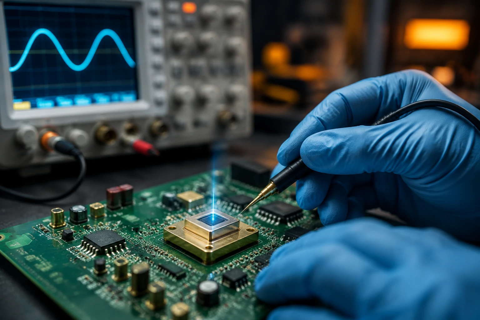
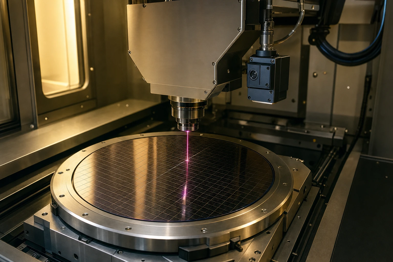
Picture this: you have spent the last three days staring at an oscilloscope, nursing a lukewarm cup of coffee, trying to figure out why your galvanometer scanner motor is humming. You zoom in on the driver board signals, and there it is—a persistent, high-frequency micro-jitter in the mirror’s position. It is not a massive swing, just a tiny wobble of a few microradians, but it is enough to make your laser engraving lines look fuzzy or ruin the accuracy of your 3D printer.
Normally, the first instinct is to open up the servo tuning software and start tweaking the PID parameters. You boost the derivative gain, back off the proportional loop, or add a notch filter. Sometimes that helps, but other times, the motor just gets hotter, and the jitter refuses to go away.
That is because the root problem is not in your digital control loop. It is in the analog feedback loop. If your optical position detector is feeding garbage noise into your transimpedance amplifier (TIA), your control loop will faithfully amplify that noise and shake your motor mirror. To stop this, you need a high-quality feedback sensor, and nothing gets the job done quite like a dedicated low noise silicon PIN photodiode. Let’s break down exactly why this quiet little piece of silicon is the secret to stabilizing your galvanometer system.
That Late-Night Analog Nightmare: Debugging Galvo Motor Hum
We have all been there. You build a beautifully compact driver board, power it up, and the motor sounds like a miniature angry bee. Galvanometers (or galvos, as we usually call them) are incredibly sensitive electromagnetic actuators. They do not rotate freely like standard DC motors; instead, they swing back and forth over a limited angle, holding a mirror that deflects a laser beam.
To keep that mirror pointing exactly where it belongs, the driver board needs to know its exact angular position at every microsecond. Most high-performance galvos use an optical position detector (PD) built right into the motor housing. A small light source, usually an infrared LED, shines onto a moving mask attached to the motor shaft. The mask casts a shadow onto a stationary photodiode array. As the shaft rotates, the light distribution on the photodiodes changes, generating a differential current.
This differential current is tiny—often in the microampere range. It goes straight to a Transimpedance Amplifier (TIA) to be converted into a readable voltage. If you are not using a high-quality low noise silicon PIN photodiode at the front end, this is where the system falls apart. A standard photodiode generates a high level of background noise and dark current. The TIA, having a high gain, turns that tiny background noise into a major voltage fluctuation. The DSP or analog controller sees this fluctuating voltage, thinks the mirror is actually moving, and drives the coils to correct for a movement that never happened. The result? High-frequency mirror vibration, motor heating, and an audible hum.
The Hidden Saboteur: Why Mirror Jitter Haunts Galvanometer Systems
To understand why mirror jitter is so hard to kill, we have to look closely at how optical feedback systems operate. When we talk about high-speed laser scanning, we are looking for settling times of under a millisecond and positioning accuracies in the microradian range.
Position Feedback Loops and the Optical Sensor Path
A standard galvanometer positioning system is a closed-loop servo. The physical components are linked in a tight circle:
- The Controller: A digital signal processor (DSP) or analog servo board calculating position error.
- The Motor Coil: An H-bridge or linear amplifier driving current into the galvo rotor to move the mirror.
- The Optical Feedback Path: An infrared light source, a physical mirror shaft mask, and a photodetector translating mechanical angle to electrical current.
- The Amplifier Stage: A transimpedance amplifier converting the sensor current to a voltage feedback signal.
When your optical feedback path is noisy, it injects random error signals into the controller. If the photodetector has a poor signal-to-noise ratio, the feedback signal lacks the resolution to distinguish between actual mechanical drift and raw electrical noise.
By using a low noise silicon PIN photodiode, you ensure that the current coming out of the sensor is a true, clean reflection of the mirror’s physical position. A quality low noise silicon PIN photodiode reduces the noise floor of the optical feedback path, allowing the controller to run at a higher gain without oscillating or introducing high-frequency jitter.
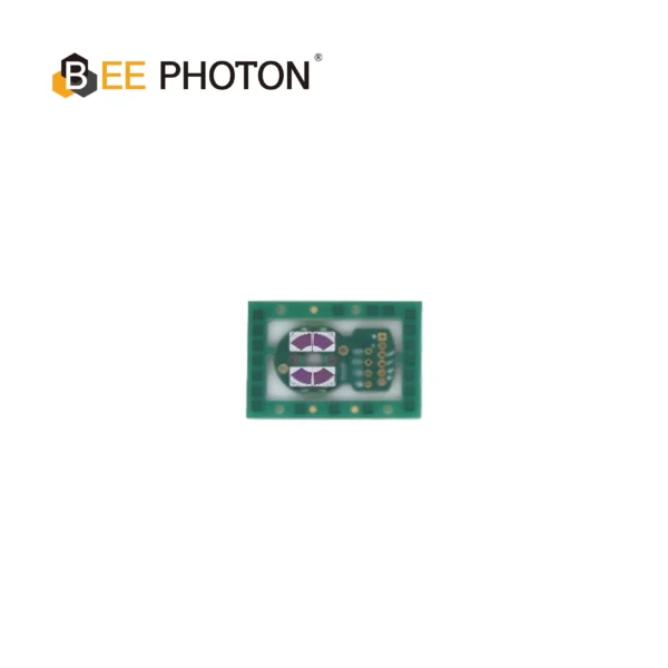
Si PIN photodiodes for Galvo PDC-2C3432-NIR-B
The PDC-2C3432-NIR-B is a specialized segmented PIN photodiode chip engineered for precise differential position feedback in high-speed galvanometer scanners. Integrating this dual-channel segmented PIN photodiode chip allows systems to obtain accurate angular tracking with minimal signal noise.
Decoding the Math of SNR Optimization Galvo Systems
Let’s roll up our sleeves and look at the physical formulas that govern this behavior. We do not need complex math programs to see what is happening under the hood; simple electronic equations show us exactly why a low noise silicon PIN photodiode is necessary for robust positioning.
The Photocurrent Signal vs the Analog Noise Floor
The ultimate goal in optical position detection is SNR optimization galvo performance. The Signal-to-Noise Ratio (SNR) in an optical detector circuit can be defined simply as:
SNR = I_p / i_total
Where I_p is the signal photocurrent generated by the light, and i_total is the total root-mean-square (RMS) noise current of the system.
The total noise current is a combination of three main factors: shot noise (i_shot), thermal (Johnson) noise from the feedback resistor (i_thermal), and the amplifier’s input noise (i_amplifier). We can write this relation as:
i_total = sqrt(i_shot^2 + i_thermal^2 + i_amplifier^2)
Now, let’s break down the shot noise. Shot noise is a physical reality of photon arrival rates and charge carriers. It is calculated using this formula:
i_shot = sqrt(2 * q * (I_p + I_d) * B)
Where:
qis the charge of an electron (approximately 1.6 x 10^-19 Coulombs).I_pis the signal photocurrent (Amperes).I_dis the photodiode dark current (Amperes).Bis the operating noise bandwidth of the circuit (Hertz).
Look at that formula closely. The dark current, I_d, sits right alongside your useful photocurrent signal, I_p, under the square root. If your photodiode has a high dark current, it directly inflates the shot noise of the system, even when the laser scanner is sitting completely still in pitch-black darkness. This is why a low noise silicon PIN photodiode with an ultra-low dark current is absolutely essential to clean up your feedback loops.
Calculating TIA Noise with a Low Noise Silicon PIN Photodiode
The thermal noise of the transimpedance amplifier’s feedback resistor (R_f) is another major piece of the puzzle. This thermal noise current is calculated as:
i_thermal = sqrt((4 * k * T * B) / R_f)
Where:
kis Boltzmann’s constant (1.38 x 10^-23 Joules per Kelvin).Tis the absolute temperature in Kelvin.R_fis the transimpedance feedback resistor value in Ohms.
To get a larger output voltage from a small photodiode current, you want a larger feedback resistor R_f. A larger R_f actually reduces the input-referred thermal noise current relative to the signal, which is great. However, your amplifier has to deal with the photodiode’s junction capacitance (C_j).
If your photodiode is a generic, high-capacitance model rather than a specialized low noise silicon PIN photodiode, that capacitance interacts with R_f to create a pole in the feedback loop. This pole reduces your circuit bandwidth and causes gain peaking at high frequencies, which amplifies the op-amp’s high-frequency voltage noise.
To prevent this stability disaster, you have to add a small feedback capacitor across R_f, which limits your system’s bandwidth. If you want high speed and high stability, you need a low noise silicon PIN photodiode that offers both low dark current and low junction capacitance.
Why You Need a Low Dark Current Photodetector in Your Design
If you ask ten analog engineers what ruins their precision sensing systems, nine of them will point to thermal drift and dark current. That is why choosing a low dark current photodetector is such a massive deal.
Thermal Drift and Dark Current Fluctuations
Dark current is the tiny current that flows through a photodiode even when there is absolutely no light shining on it. It is caused by the thermal generation of electron-hole pairs within the depletion region of the silicon.
Here is the real problem: dark current is not static. It increases exponentially with temperature. As a rule of thumb, dark current doubles for every 8 to 10 degrees Celsius increase in temperature.
In a galvanometer system, the motor coils generate a lot of heat during rapid scanning profiles. This heat travels up the shaft and warms the internal optical position sensor housing. If you are not using a low noise silicon PIN photodiode with a stable temperature coefficient, your feedback signal baseline will drift wildly as the scanner warms up. The DSP will see this drift as a physical shift in mirror position, causing your laser beam to slowly drift away from its target over hours of operation.
By integrating a specialized low noise silicon PIN photodiode like those designed by BeePhoton, you lock down that drift. Their chips are manufactured with tight tolerances and specialized silicon structures that keep dark currents down to single-digit picoamperes (pA) at low bias voltages, ensuring excellent thermal stability.
Mastering TIA Noise Reduction Photodiode Electronics
Selecting the right photodiode is the first step, but you also have to pair it with the right amplifier circuit. When you are designing a high-speed feedback loop, you want to focus heavily on TIA noise reduction photodiode matching.
The Hidden Impact of Junction Capacitance
When you set up your transimpedance amplifier, the op-amp’s voltage noise (e_n) is amplified by the “noise gain” of the circuit. At high frequencies, this noise gain is determined by the ratio of the photodiode’s junction capacitance to the feedback capacitance.
If your photodiode’s junction capacitance (C_j) is high, your TIA’s high-frequency noise gain skyrockets. You end up with a high-frequency noise floor that eats into your dynamic range.
Using a high-performance low noise silicon PIN photodiode is the easiest way to solve this. Because PIN photodiodes have an intrinsic (undoped) layer between the P and N regions, they naturally have a much wider depletion region, which translates to a vastly lower junction capacitance than standard PN photodiodes. This physical property allows you to maintain high bandwidth and exceptionally low noise gain in your TIA stage.
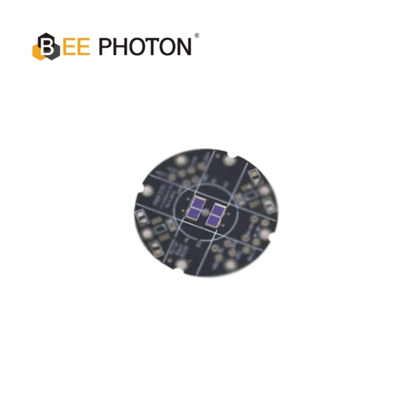
Si PIN photodiodes for Galvo PDC-C2929
The PDC-C2929 is a budget-friendly 920nm silicon PIN photodiode chip. This 920nm silicon PIN photodiode offers stable, cost-effective scanner position tracking.
A Deep Dive into High-Performance Silicon Components
When it comes to selecting actual silicon for your board design, generic components off the shelf usually do not cut it. You need chips engineered specifically for galvanometer position detectors. Let’s look at three leading options available from BeePhoton that are designed to solve these exact analog feedback problems.
Comparing Low Noise Silicon PIN Photodiode Chips
To help you choose the right component for your layout, here is a breakdown of three stellar silicon PIN options. Each of these models serves a slightly different niche, depending on whether you are designing a budget-conscious system, a ultra-precise laser marker, or a high-speed differential scanner.
| Parameter | PDC-C2928-NIR-B silicon PIN photodiode chip | PDC-C2929 silicon photodiode | PDC-2C3432-NIR-B segmented PIN photodiode chip |
|---|---|---|---|
| Photosensitive Area Shape | Square | Square | 2-Segment Fan Shape |
| Active Area Size | 2.9 mm x 2.8 mm | 2.9 mm x 2.9 mm | Dual Segments |
| Spectral Range | 340 nm to 1100 nm | 450 nm to 1100 nm | 340 nm to 1100 nm |
| Peak Sensitivity Wavelength | 940 nm | 920 nm | 940 nm |
| Photosensitivity @ Peak | 0.65 A/W | 0.72 A/W | 0.65 A/W |
| Typical Dark Current (V_R=10mV) | 5 pA | 15 pA | 5 pA |
| Max Dark Current (V_R=10mV) | 50 pA | 500 pA | 500 pA |
| Junction Capacitance (Typ.) | 125 pF | 70 pF | 85 pF |
| Rise Time (R_L=1kOhm, V_R=0V) | 0.27 microseconds | 0.15 microseconds | 0.18 microseconds |
| Typical Shunt Resistance | 2 Gigaohms | 0.5 Gigaohms | 2 Gigaohms |
If you are looking for the absolute gold standard in single-channel feedback, the PDC-C2928-NIR-B silicon PIN photodiode chip is an incredible piece of work. With a typical dark current of just 5 pA and a massive 2 Gigaohm shunt resistance, it is built to keep your feedback signals whisper-quiet.
For high-end differential positioning where you need segmented tracking, the PDC-2C3432-NIR-B segmented PIN photodiode chip offers a dual-channel fan-shaped design that allows you to calculate differential position with extreme precision.
On the other hand, if you are designing a cost-sensitive industrial scanner and need to keep your bill of materials (BOM) in check without sacrificing baseline stability, the PDC-C2929 silicon photodiode provides a robust 70 pF junction capacitance and highly consistent response at a budget-friendly price point.
An Honest Case Study: Rescuing an Industrial Laser Engraver
Let’s step away from the formulas for a second and talk about how this plays out in the real world. A couple of years ago, an industrial laser engraving manufacturer in Europe was hitting a wall. They were developing a high-speed laser marker designed to engrave serial numbers on anodized aluminum at a rate of 500 characters per second.
During testing, they noticed that the edges of their engraved letters had a tiny, feather-like fuzziness. When they zoomed in under a digital microscope, they realized the laser was wobbling back and forth by about 12 microradians during high-speed moves. This made the text look unprofessional and hard for automated barcode readers to scan.
The firmware team spent three weeks rewriting their servo filter code. They tried Kalman filters, low-pass averaging, and custom notch filters. Nothing worked. If they filtered the signal too much, the system suffered from massive phase lag and overshot the corners. If they did not filter it, the jitter returned.
Finally, they looked at the position detector board inside the scanner motor. They were using a cheap, off-the-shelf PIN diode with a dark current of around 200 pA and a junction capacitance of nearly 400 pF.
The engineers decided to drop in a low noise silicon PIN photodiode—specifically, the PDC-C2928-NIR-B silicon PIN photodiode chip from BeePhoton. Because of its tight 5 pA dark current and optimized 940 nm near-infrared (NIR) sensitivity, the baseline noise coming out of the optical sensor dropped by over 15 dB.
The difference was like night and day. With a clean, noise-free analog feedback signal, they were able to crank up their servo controller gains. The feathering on the laser engraving disappeared completely, and the settling time of the galvo improved by 20%. They did not have to write a single line of new filter code—they just fixed the analog signal source.
Actionable PCB Layout Hacks for SNR Optimization Galvo Boards
If you want to get the absolute best performance out of your low noise silicon PIN photodiode, you cannot just solder it down and hope for the best. You need a layout that respects the micro-signals flowing through your board. Here are some quick, practical hardware design tips for your next layout revision:
- Keep the TIA Close: Place your transimpedance amplifier op-amp as physically close to the photodiode chip as possible. Every millimeter of trace between the photodiode anode and the TIA input acts like an antenna that picks up switching noise from your driver’s digital lines or the motor’s power H-bridge.
- Use a Guard Ring: Run a copper guard ring around the high-impedance input traces of your TIA. Connect this guard ring to a low-impedance voltage source that matches the potential of the photodiode’s terminal. This prevents surface leakage currents on the FR4 board from sneaking into your signal path.
- Split Your Ground Planes: Keep your analog signal ground (used by the photodiode and TIA) separate from your noisy digital and power grounds (used by the DSP and H-bridge). Connect them at a single “star ground” point right near the power entry connector. This prevents motor return currents from modulating your sensor’s ground reference.
- Shield the Sensor Assembly: If your galvo operates in an electromagnetically noisy environment, consider placing a small metal shield can over the photodiode and TIA stage. This blocks capacitive coupling from nearby high-current motor cables.
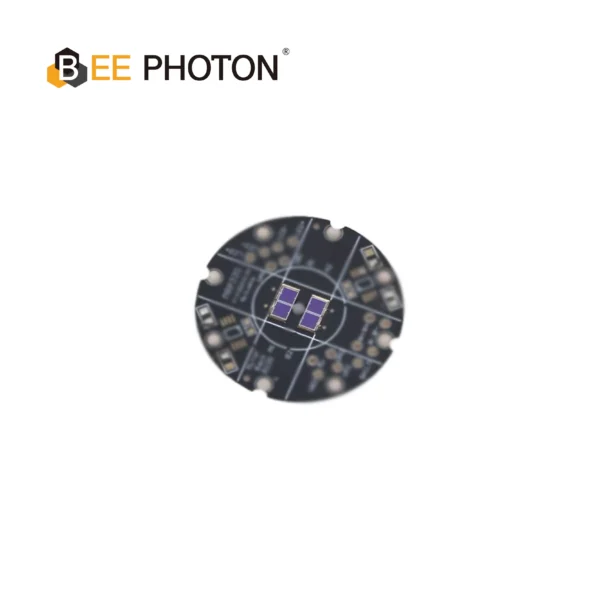
Si PIN photodiodes for Galvo PDC-C2928-NIR-B
Optimize scanning with our 940nm PIN photodiode chip, PDC-C2928-NIR-B. This 940nm PIN photodiode chip ensures precise galvo position sensing and low noise.
Frequently Asked Questions on Optical Galvo Feedback
Why is a PIN photodiode better than a standard PN photodiode for galvo feedback?
A standard PN photodiode has a narrow depletion region, which leads to high junction capacitance. High capacitance slows down the sensor’s response and increases the noise gain of your transimpedance amplifier. A low noise silicon PIN photodiode features an extra, undoped intrinsic layer that widens the depletion region. This dramatically lowers the junction capacitance, giving you much higher speeds and a significantly quieter feedback signal.
How does reducing dark current help with temperature stability?
Dark current doubles roughly every 8 to 10 degrees Celsius. Because galvanometers generate significant physical heat during operation, the sensor housing temperature rises. If your photodetector has a high initial dark current, this thermal rise causes the baseline signal to drift, leading to position drift in your laser beam. Choosing a low noise silicon PIN photodiode with a low dark current limits this thermal baseline variation to a negligible level.
Can I use a visible-light photodiode for my position feedback sensor?
You can, but it is usually a bad idea. Industrial laser systems often have a lot of ambient visible light, laser scattering, or indicator LEDs nearby. If your photodiode is sensitive to visible light, it will pick up this stray light and inject it as noise into your loop. Using a near-infrared (NIR) optimized low noise silicon PIN photodiode like the PDC-C2928-NIR-B silicon PIN photodiode chip (optimized for 940 nm) along with a matching infrared light source allows you to easily filter out ambient visible light noise.
Is it necessary to apply a high reverse bias voltage to the photodiode?
While applying a reverse bias voltage decreases junction capacitance and increases speed, it also increases the photodiode’s dark current. For position feedback systems where low noise and thermal stability are critical, running the photodiode at a very low reverse bias (or even zero bias, known as photovoltaic mode) is often preferred. High-quality low noise silicon PIN photodiode chips are specifically optimized to deliver fast response times even at low bias voltages like 10mV.
Elevate Your Laser Precision with BeePhoton
If you are tired of chasing mysterious motor vibrations and want to build a galvanometer scanner that runs quiet, cool, and incredibly sharp, it is time to upgrade your feedback path.
The team at BeePhoton has spent years perfecting high-reliability photon detection components. From high-speed linear detector cards to ultra-stable silicon sensor chips, they design optical components that handle the messy physical realities of high-power industrial environments.
Whether you need a drop-in replacement like the PDC-C2928-NIR-B silicon PIN photodiode chip or a completely customized multi-segment sensor array tailored to your custom motor shaft housing, their application engineers can help you get your design right.
Do not let high-frequency noise compromise your system’s performance. Clean up your analog signals, optimize your SNR, and build a system you can be proud of. To request datasheets, order samples, or discuss your custom optical layout requirements, feel free to contact us directly or send an email to our engineering team at info@photo-detector.com. Let’s build something incredibly precise together!