You’re halfway through your front-end design, staring at the schematic, and the question hits again: should I run this photodiode in photovoltaic mode or photoconductive mode? One gives you beautiful low noise. The other gives you speed. Pick the wrong one and you’ll spend weeks chasing ghosts in the signal.
After spending way too many nights in the lab with Si PIN photodiodes, I’ve learned the hard way that there isn’t one “best” answer. There’s only the right answer for your application. Let’s talk about how to actually make that call.
What Photovoltaic Mode Actually Is (and Why Zero Bias Matters)
Photovoltaic mode means running the photodiode at zero bias — no external voltage across it. The diode generates current purely from incident light, like a tiny solar cell.
The biggest advantage? Extremely low dark current. We’re often talking single-digit picoamps or even lower with good Si PIN photodiodes. That translates directly into lower noise, especially at low light levels where every electron counts.
I remember one medical spectroscopy project where we were trying to measure absorbance changes of 0.001 AU. In photovoltaic mode the noise floor stayed low enough that we didn’t need heroic averaging. When we tried switching to reverse bias later, the increased dark current wrecked our signal-to-noise ratio within minutes.
The formula for photocurrent stays the same in both modes:
Iph = R × P
Where R is responsivity (A/W) and P is optical power. But the noise current is where things get interesting. In photovoltaic mode your dominant noise sources are usually Johnson noise from the feedback resistor and the op-amp’s current noise. The photodiode’s own shot noise from dark current is almost negligible.
Photoconductive Mode — Speed at a Cost
Flip the situation around and apply reverse bias. Now you’re in photoconductive mode.
The reverse voltage does two useful things:
- It widens the depletion region, reducing junction capacitance (Cj).
- It increases the electric field, speeding up carrier collection.
Lower Cj means higher bandwidth. The relationship is roughly:
Cj ∝ 1 / √(Vbi + Vr)
Where Vbi is the built-in voltage (~0.7V for silicon) and Vr is your reverse bias.
I’ve measured bandwidth improvements of 3–5× when moving from 0V to –10V on standard 1mm² Si PIN photodiodes. That’s huge when you’re designing a 100MHz TIA.
But here’s the trade-off nobody puts in the marketing slides: dark current jumps dramatically. What was 5pA at zero bias can easily become 500pA or several nanoamps at –10V, depending on the device and temperature. And remember, shot noise goes with the square root of current. That noise is now in your signal chain whether you like it or not.
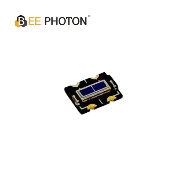
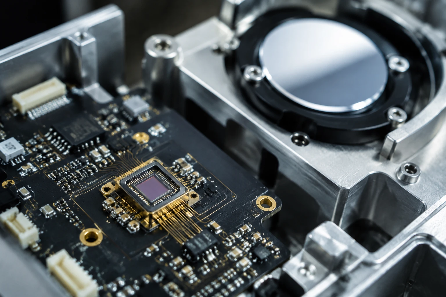
Si PIN Photodiode Array PDCA02-601
The Bee Photon PDCA Series is a precision-engineered Dual PIN Photodiode designed for high-end industrial sensing. Unlike standard single-element detectors, this silicon-based device features a segmented array structure (PD A and PD B), making it the perfect solution for differential sensing and background suppression optical switches. With a wide spectral response from 350nm to 1060nm, it ensures versatile performance across visible and near-infrared wavelengths.
Head-to-Head Comparison Table
| Parameter | Photovoltaic Mode (0V) | Photoconductive Mode (Reverse Bias) | Winner Depends On |
|---|---|---|---|
| Dark Current | Very low (pA range) | 10–1000× higher | Noise critical applications |
| Junction Capacitance | Higher | Significantly lower | High bandwidth needs |
| Bandwidth | Limited by RC time constant | Much higher | Speed requirements |
| Noise Floor | Excellent | Degraded by dark current shot noise | Low light levels |
| Linearity | Outstanding | Good but can show saturation effects | Precision measurement |
| Power Consumption | None from bias supply | Small but present | Battery powered devices |
| Temperature Sensitivity | Lower dark current drift | Higher temperature dependence | Uncontrolled environments |
This table isn’t theoretical — it’s what I’ve measured across dozens of BeePhoton Si PIN photodiodes and competitor parts over the years.
When I Recommend Photovoltaic Mode
If you’re measuring DC or low-frequency signals and care about every last photon, start with photovoltaic mode. Think:
- Precision optical power meters
- Low-light spectroscopy
- Medical diagnostics (pulse oximetry, fluorescence)
- Environmental monitoring
The lack of bias voltage also simplifies your PCB layout. No extra power rail, fewer decoupling concerns, and generally easier EMI control.
One customer (an industrial sensor company) came to us after struggling with temperature drift in their previous design. They were using –5V bias on photodiodes that didn’t need the speed. Switching them to photovoltaic mode with our Si PIN photodiodes cut their temperature coefficient in half and simplified the power supply section. Their words, not mine: “We over-engineered the hell out of it.”
When Photoconductive Mode Makes Sense
High-speed applications almost always need photoconductive mode. I’m talking about:
- Optical communication receivers
- LIDAR front-ends
- High-speed scanning systems
- Time-of-flight measurements
The reduced capacitance lets you use a smaller feedback resistor while maintaining bandwidth, which improves your noise gain. That’s critical in transimpedance amplifiers.
Here’s a practical example. We worked with a team building a 50MHz optical sensor for industrial automation. Their original photovoltaic mode design topped out at 12MHz before the signal started rolling off. Moving to –8V bias and re-optimizing the TIA got them to 55MHz with acceptable noise. Sometimes you just need the speed.
How This Choice Affects Your TIA Design
This is where most hardware engineers get bitten.
In photovoltaic mode, your TIA stability is usually easier to achieve because the photodiode capacitance is higher but constant. You can often use larger feedback resistors.
In photoconductive mode, the lower (but voltage-dependent) capacitance changes your loop stability. I’ve seen plenty of designs that looked perfect on paper but oscillated when the reverse bias was applied because the designer didn’t account for the changing Cj.
The feedback capacitor (Cf) calculation changes too. The formula most people use is:
Cf = √(2π × Rf × Cin × fu) / (2π × Rf × fu)
Where fu is the unity-gain bandwidth of your op-amp and Cin includes the photodiode capacitance.
Notice how Cin changes dramatically between modes? Yeah. That’s why copying a reference design without understanding the bias condition is dangerous.
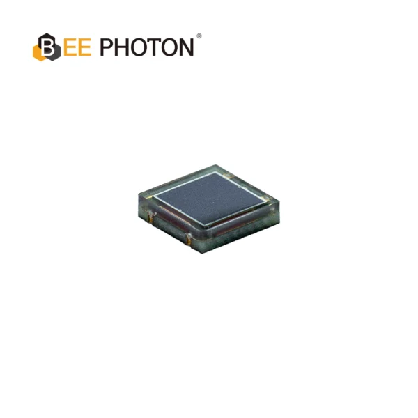
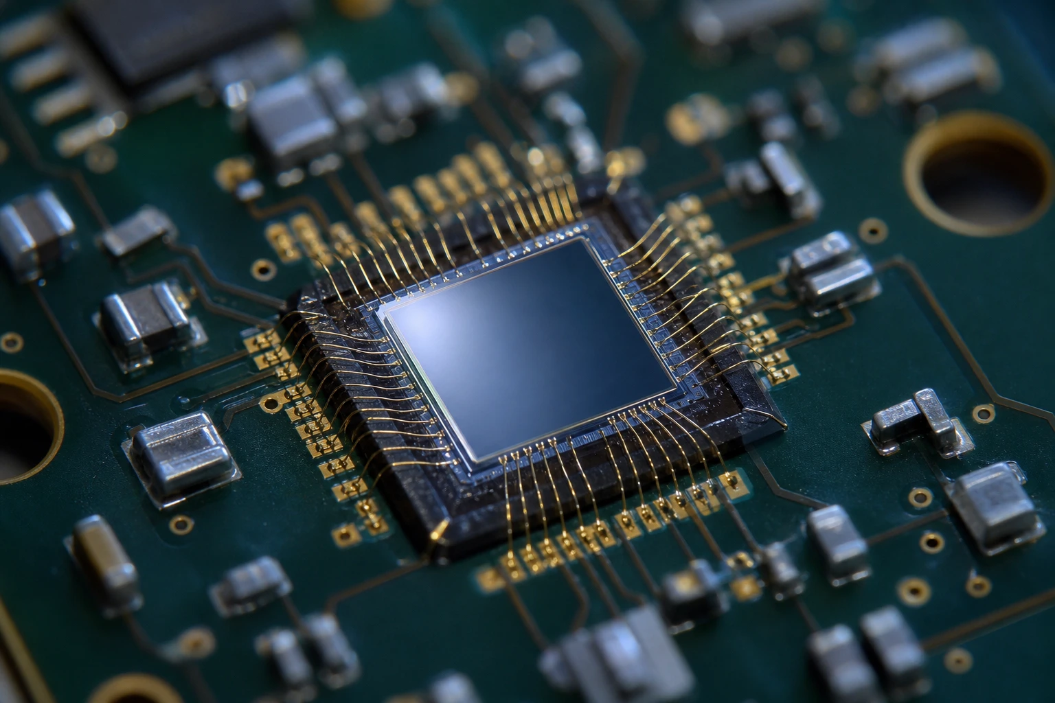
Si PIN Photodiode with low dark current (350-1060nm) PDCC34-001
Bee Photon offers a compact COB Si PIN Photodiode with wide spectral response (350-1060nm). This Chip-on-Board photodiode features low dark current, ideal for integrated and space-constrained applications.
Practical Tips From the Bench
- Measure, don’t assume. The datasheet typical values are just that — typical. Characterize your actual photodiodes in both modes.
- Temperature matters more than you think. Dark current roughly doubles every 10°C. A part that looks fine at 25°C in photoconductive mode might be unusable at 60°C.
- Consider bootstrapping. There are clever circuits that apply bias but cancel out the dark current. We’ve used them successfully in a few scientific instruments.
- Don’t forget the op-amp choice. Low bias current FET op-amps are usually better for photovoltaic mode. Sometimes faster BJT amps work better in photoconductive applications despite higher current noise.
Our Si PIN photodiodes were specifically designed with these trade-offs in mind. The package and chip geometry give particularly clean performance at zero bias while still handling moderate reverse voltage without breaking down early.
Real Talk About Common Mistakes
The biggest mistake I see is defaulting to photoconductive mode “because bandwidth.” Many applications don’t actually need that bandwidth. Running at zero bias would have given them 6–10dB better signal-to-noise ratio with zero extra effort.
Another classic: ignoring the increased noise when calculating system dynamic range. You might gain bandwidth but lose effective bits. That’s not a win.
I’ve also seen people apply way too much reverse voltage. For most silicon PIN photodiodes, –10V to –20V is plenty. Going to –70V doesn’t buy you much more speed but destroys your dark current and risks reliability.
Making the Decision Framework
Here’s the mental checklist I use now:
- What’s my required bandwidth?
- What’s the minimum optical signal I need to detect?
- What’s my maximum acceptable noise?
- Do I have tight temperature control?
- How much complexity am I willing to add to the power supply?
If bandwidth is below about 5–10MHz and you need every bit of dynamic range, I’d start with photovoltaic mode. Above 20MHz, you’re probably heading toward photoconductive mode whether you like it or not.
The gray area in the middle (5–20MHz) is where the real engineering happens. That’s where understanding both modes deeply pays off.
Ready to Move Forward?
Look, designing the perfect photodiode front-end is hard enough without guessing at the fundamental operating mode. The difference between getting photovoltaic vs photoconductive mode right can be the difference between a product that works beautifully and one that barely scrapes by.
If you’re wrestling with this choice right now, we’d genuinely like to help. The team at BeePhoton has worked with hundreds of hardware engineers on exactly these problems.
Head over to our contact page and tell us about your project. Whether you need advice on TIA topology, want to discuss specific Si PIN photodiode characteristics, or just want to get some sample parts to test both modes yourself, we’re here for it.
You can also email us directly at info@photo-detector.com. Sometimes the fastest way to answer the photovoltaic vs photoconductive mode question is to put real parts on the bench and measure.

Si PIN Photodiode with low dark current (350-1060nm) PDCC14-001
Our Si PIN for precision photometry delivers exceptional accuracy for sensitive light measurement. With low dark current, this photodiode is ideal for analytical and scientific instruments requiring precise results.
Frequently Asked Questions
Q: Can I switch between photovoltaic and photoconductive mode in the same design?
A: Yes, but you need to be careful. The compensation capacitor that stabilizes your TIA in one mode might cause peaking or oscillation in the other. If you truly need both, design for the worst-case stability condition and consider using a digital potentiometer or switched capacitor network to adjust compensation.
Q: Does photovoltaic mode always mean lower noise?
A: Almost always at low frequencies and low light levels. But at very high frequencies, the higher capacitance in photovoltaic mode can force you to use a smaller feedback resistor, which increases Johnson noise. The crossover point depends on your specific photodiode, op-amp, and bandwidth requirements.
Q: What’s the typical reverse bias voltage used in photoconductive mode?
A: For most Si PIN photodiodes, –5V to –15V is the sweet spot. Going beyond –20V usually gives diminishing returns on bandwidth while dramatically increasing dark current. Always check the datasheet maximum rating — some of our higher speed parts are characterized up to –30V but most standard devices perform best below –10V.
Q: How do I know if my application needs the speed of photoconductive mode?
A: Look at your signal’s rise time requirement. If you need to resolve events faster than about 30ns, you’re probably entering the region where photoconductive mode becomes necessary. For anything slower, start with zero bias and only add reverse voltage if measurements prove you need it.
The choice between photovoltaic mode and photoconductive mode isn’t about which is better. It’s about which one is right for your circuit, your signal, and your constraints. Get that part right and the rest of the design gets a whole lot easier.