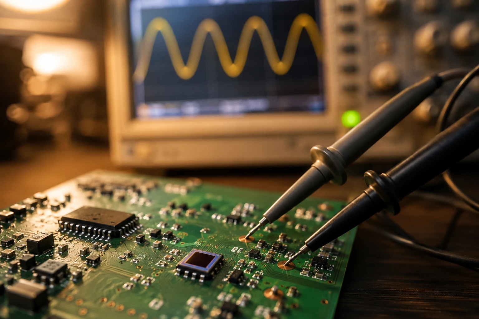
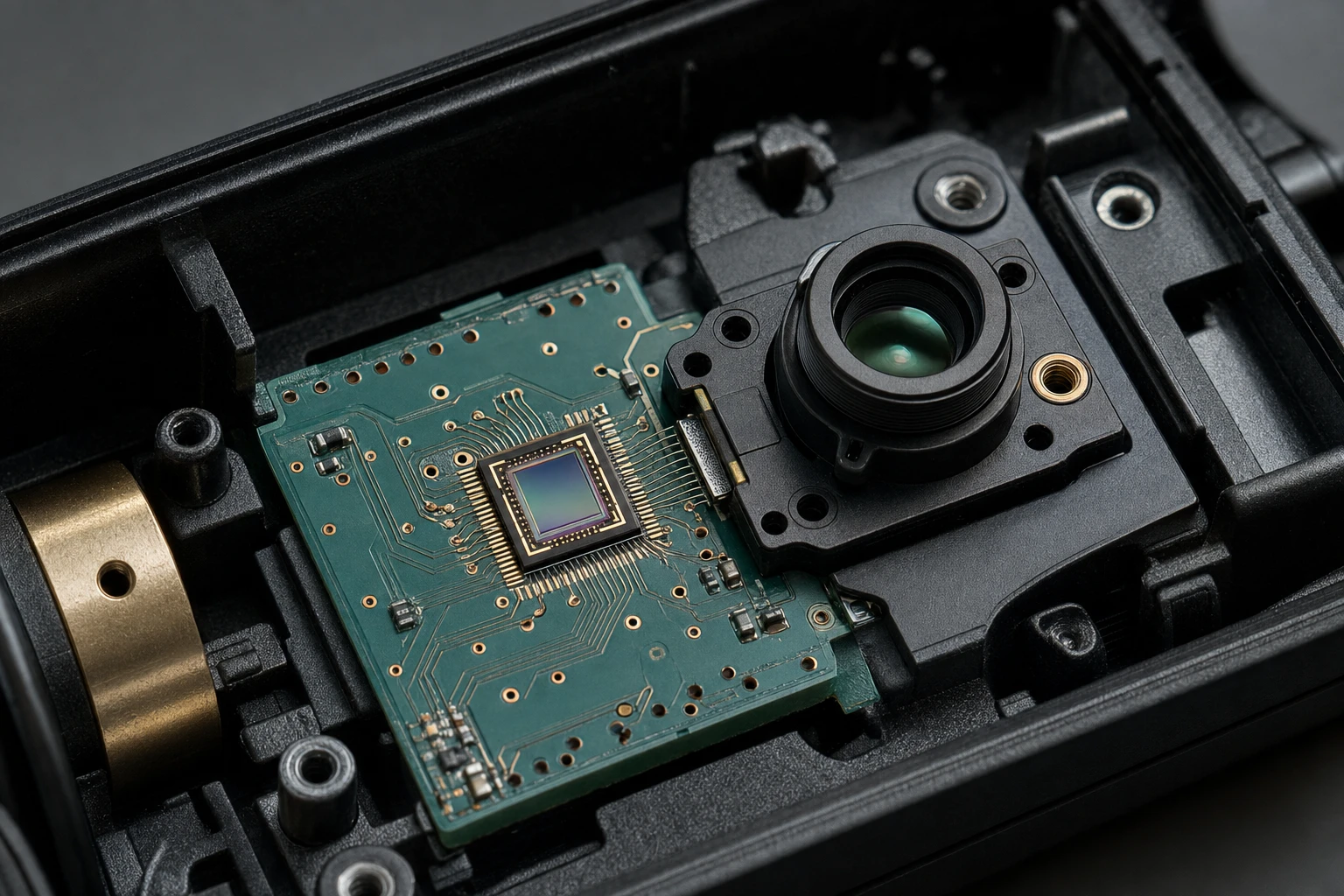
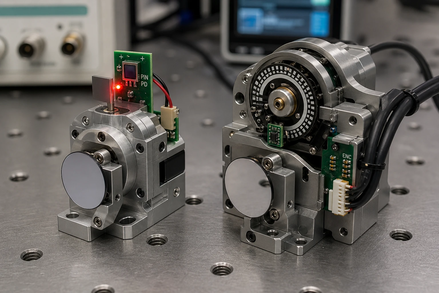
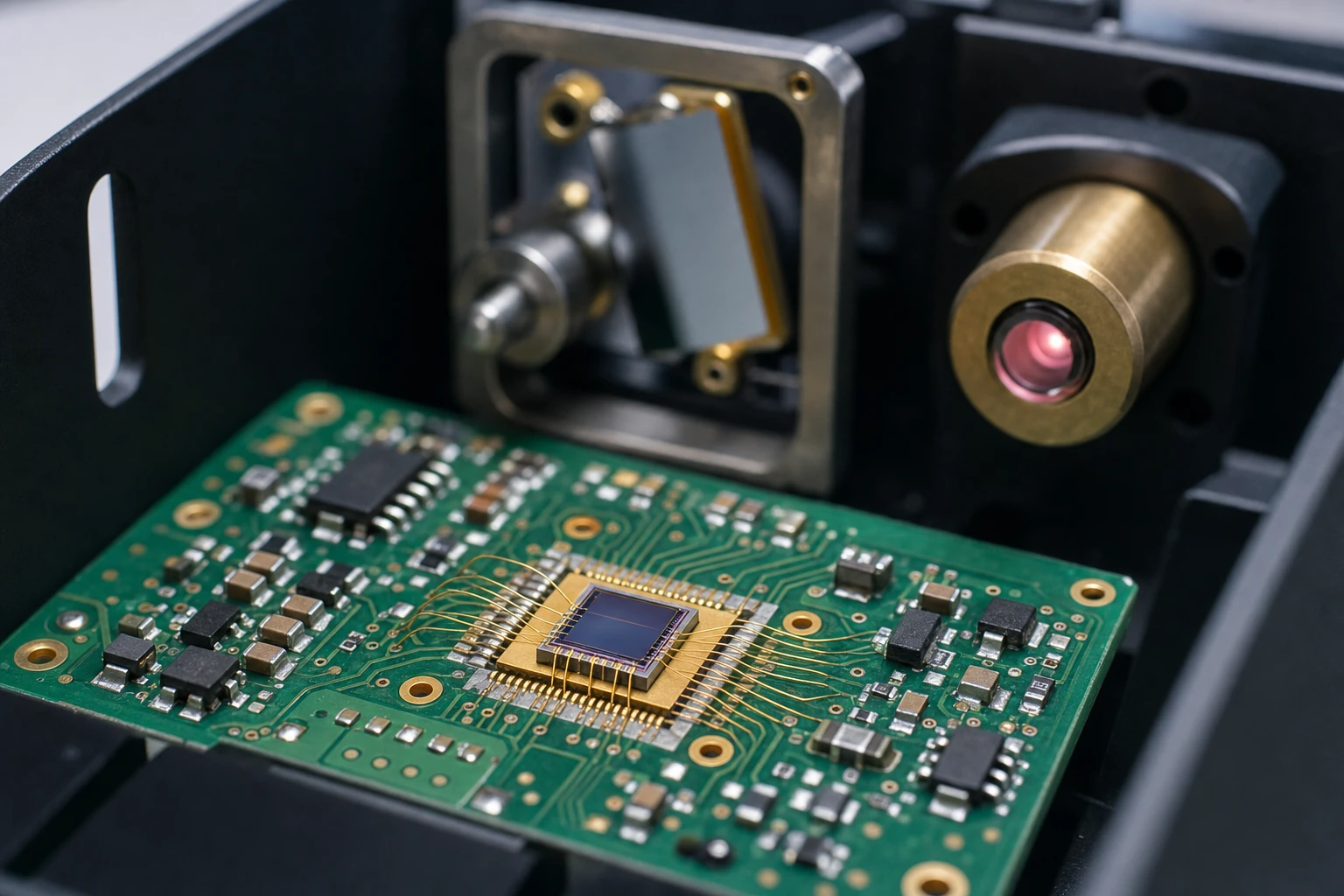
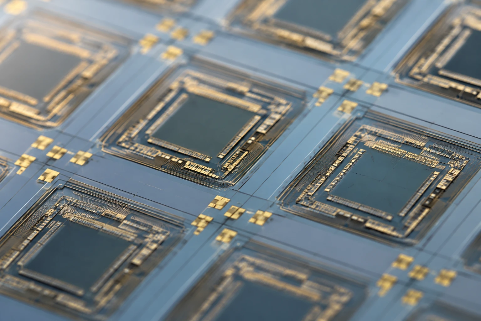
If you are an R&D engineer designing high-precision optical sensors, you have probably faced the classic dilemma of choosing the right wavelength. While the standard 850nm wavelength gets most of the industry spotlight, the specialized 855nm NIR LED is quietly solving some of the toughest alignment and filtering issues in high-resolution scanning, rotary encoders, and industrial optical barriers.
At first glance, a 5nm difference seems trivial. After all, what is 5 nanometers when you are dealing with a broad near-infrared spectral curve? But in the world of high-performance optoelectronics, that tiny offset can represent the difference between a sensor that drifts out of spec in warm temperatures and one that operates reliably for years.
Let’s dive into the core differences between a standard 850nm emitter and an 855nm NIR LED so you can make the best choice for your next prototype.
Decoding the Basics: What is an 855nm NIR LED?
An 855nm NIR LED is a near-infrared light-emitting diode specifically engineered to emit light with a peak spectral distribution centered at 855 nanometers. Most of these diodes are fabricated using Gallium Aluminum Arsenide (GaAlAs or AlGaAs) semiconductor materials. By adjusting the ratio of aluminum to gallium in the active layers during the metal-organic chemical vapor deposition (MOCVD) growth process, engineers can fine-tune the bandgap to target this exact wavelength.
In B2B industrial applications, we often recommend the 855nm NIR LED for tasks requiring tight spatial control, highly collimated beams, or specific matching with narrow-bandpass optical filters. While standard LEDs are designed to emit as much raw light power as possible across a wide angle, a premium 855nm NIR LED is frequently designed as a point source emitter. This means the light is restricted to a microscopic emitting area, making it an excellent candidate to collimate.
The Nanometer Showdown: 850nm vs 855nm IR LED
When comparing a standard 850nm source with an 855nm NIR LED, we are looking at two emitters that share the same general near-infrared band (IR-A). However, their real-world performance characteristics differ in key physical and optical areas.
Semiconductor Physics: Wavelength vs. Bandgap
To understand why these two wavelengths differ, we have to look at the semiconductor bandgap. The peak wavelength of a light-emitting diode is inversely proportional to the bandgap energy of the active layer. We can express this using a simple, universal formula:
Wavelength (lambda) = (h * c) / Eg
To make this practical for optical engineering, we can simplify it:
Wavelength (in nm) ≈ 1240 / Eg (in eV)
If we rearrange this to find the bandgap energy (Eg) for both emitters:
- For a standard 850nm emitter: Eg ≈ 1240 / 850 = 1.459 eV
- For an 855nm NIR LED: Eg ≈ 1240 / 855 = 1.450 eV
This tiny difference of 0.009 electronvolts might seem microscopic, but it changes how the material behaves under thermal stress. Because the 855nm NIR LED has a slightly lower bandgap energy, it naturally operates with a marginally lower forward voltage (Vf) at the exact same drive current.
Power Output vs. Peak Wavelength Stability
Historically, standard 850nm LEDs have enjoyed a massive advantage in raw optical output power. Because 850nm is the default wavelength for security cameras and consumer remote controls, the manufacturing scale is enormous. If you just need to flood an area with infrared light, 850nm is highly cost-effective.
However, if your sensor relies on a highly stable peak wavelength, a standard 850nm LED can be a liability. Mass-produced 850nm LEDs often have wider spectral bandwidths—measured as Full Width at Half Maximum (FWHM)—typically ranging from 30nm to 50nm.
An 855nm NIR LED, especially when sourced from specialized manufacturers like BeePhoton, is often binned and processed to have a tighter spectral width (sometimes under 25nm FWHM) and highly stable peak emission under continuous-wave (CW) drive conditions.
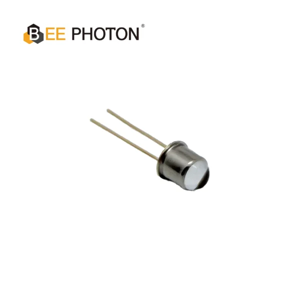
NIR LED E850-180-201L4
The E850-180-201L4 is a high-performance 850nm NIR LED engineered for precision industrial sensing. Manufactured by Bee Photon, this infrared emitter is designed to deliver high luminosity and exceptional stability, making it the ideal light source for demanding automation environments.
Point Source vs. Surface Emitter: Why the 855nm NIR LED Wins in Precision Optical Sensors
The biggest differentiator between a generic 850nm LED and a precision 855nm NIR LED is often the internal structure of the chip itself.
Standard 850nm LEDs are typically “surface emitters.” The entire top surface of the semiconductor die glows, but this glow is interrupted by the wire bond pad in the middle of the chip. This creates a messy emission profile with a dark spot right where your optical system expects the brightest light. For security illumination, this does not matter. For a sub-micron optical encoder, it is a problem.
This is where the specialized 855nm NIR LED point source enters the picture.
In a standard surface emitter (typical 850nm), a wire bond pad is placed right in the middle of the active emitting region, causing a noticeable dark spot in the center of the output beam and creating a diffuse light pattern.
In a point source emitter (typical 855nm), a masking layer is deposited over the semiconductor structure, featuring a micro-aperture that restricts light emission to a tiny, uniform circular window (e.g., 50 to 150 micrometers). The wire bond is connected to the masking layer outside the aperture, meaning there is no wire shadow and the beam is incredibly uniform.
Eliminating the Penumbra Effect in Rotary Encoders
If you are designing a high-resolution rotary or linear optical encoder, your emitter needs to project a shadow of a moving grating onto a photodiode array. If your light source has a large emitting area, it will create a fuzzy shadow edge known as a penumbra.
The width of this fuzzy edge (P) is determined by the emitter’s aperture diameter (d), the distance from the emitter to the grating (g), and the distance from the grating to the detector (D):
P = d * (D / g)
If you use a standard 850nm surface emitter with an effective chip diameter of 300 micrometers, your penumbra will be relatively wide, causing phase errors and limiting your encoder’s resolution.
If you swap that out for an 855nm NIR LED point source with a 50-micrometer aperture, the penumbra shrinks by a factor of six! The resulting shadows are razor-sharp, allowing you to read much finer grating pitches without signal degradation.
Managing Temperature Shifts in an 855nm NIR LED
When running a sensor in an industrial environment, temperature is your constant enemy. All AlGaAs-based infrared emitters suffer from a physical phenomenon known as thermal redshift: as the junction temperature rises, the bandgap shrinks, and the peak emission wavelength shifts to a longer wavelength.
For most near-infrared diodes, this temperature coefficient (alpha_T) is relatively constant:
alpha_T ≈ 0.25 nm/°C to 0.30 nm/°C
The Math Behind Temperature-Induced Redshift
Let’s look at how this thermal shift affects an 855nm NIR LED under typical operating conditions. We can calculate the operating peak wavelength using this linear approximation:
lambda(T) = lambda_0 + alpha_T * (T_junction – T_0)
Where:
- lambda(T) is the peak wavelength at operating temperature.
- lambda_0 is the peak wavelength at room temperature (usually 855nm at 25°C).
- alpha_T is the thermal shift coefficient (we will use 0.26 nm/°C).
- T_junction is the actual temperature of the semiconductor junction.
- T_0 is the reference temperature (25°C).
To find the junction temperature (T_junction), we must calculate the thermal rise caused by the drive current:
T_junction = T_ambient + (Power_dissipated * R_thermal)
Let’s plug in some realistic numbers for a high-quality 855nm NIR LED packaged in a TO-46 metal can:
- Ambient Temperature (T_ambient) = 55°C (inside a sealed industrial sensor housing).
- Forward Current (If) = 80 mA.
- Typical Forward Voltage (Vf) = 1.6 V.
- Package Thermal Resistance (R_thermal) = 150°C/W.
First, calculate the power dissipation:
Power_dissipated = Vf * If
Power_dissipated = 1.6 V * 0.08 A = 0.128 W
Now, calculate the junction temperature:
T_junction = 55°C + (0.128 W * 150°C/W)
T_junction = 55°C + 19.2°C = 74.2°C
Finally, calculate the shifted peak wavelength:
lambda(T) = 855 nm + 0.26 nm/°C * (74.2°C – 25°C)
lambda(T) = 855 nm + 0.26 nm/°C * (49.2°C)
lambda(T) = 855 nm + 12.8 nm ≈ 867.8 nm
At an internal operating temperature of 74.2°C, our 855nm NIR LED is actually peaking at nearly 868nm!
Why This Matters for Narrow Bandpass Filters
In many outdoor or high-ambient-light industrial environments, your sensor’s receiver needs to ignore sunlight and overhead factory lighting. To do this, engineers place an optical bandpass filter in front of the photodiode.
If you design your receiver with a very tight bandpass filter centered exactly at 850nm with a bandwidth of 10nm (meaning it only passes light from 845nm to 855nm), a standard 850nm LED running hot will quickly drift out of the passband.
For instance, at room temperature, a standard 850nm LED fits perfectly within the 845nm to 855nm transmission window. However, when operating in high ambient heat, the peak wavelength of that standard emitter redshifts to 861nm, which falls entirely outside the filter’s passband, causing a massive loss of optical signal.
By understanding this drift, you can make an informed choice. Some engineers specifically use an 855nm NIR LED paired with an 860nm or 865nm bandpass filter. This ensures that as the system warms up to its stable operating temperature, the emitter’s peak wavelength drifts directly into the sweet spot of the filter’s transmission curve, rather than drifting out of it.
Narrow Beam IR Diode: Is the 855nm NIR LED Easily Collimated?
Yes, a narrow beam IR diode based on an 855nm NIR LED is much easier to collimate than standard wide-angle emitters. Because the point source design concentrates light emission into a tiny physical area, you can place a collimating lens very close to the chip.
This allows you to project a tight, parallel beam over long distances with minimal beam divergence (often under 5 degrees half-angle). If you are building optical light curtains, edge detection sensors, or reflective scanners, this narrow beam prevents optical crosstalk and ensures that only the target object interrupts the light path.
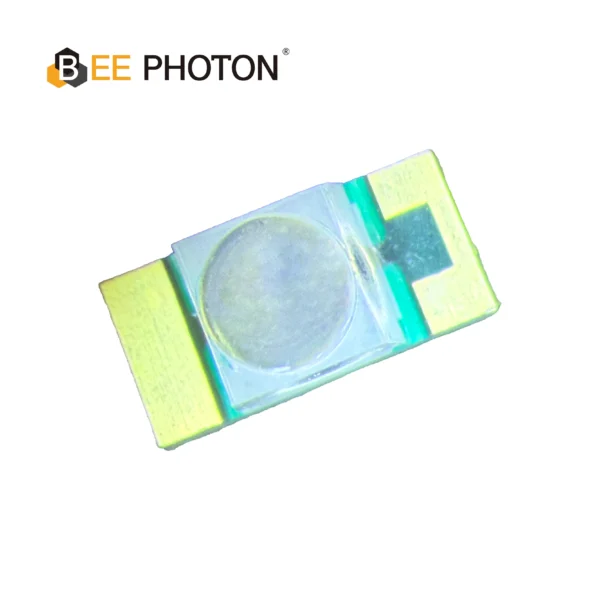
NIR LED E850-25-001-L20
The E850-25-001-L20 is a high-performance 855nm NIR LED designed for demanding industrial applications. Manufactured by Bee Photon, this infrared emitter features a narrow 20-degree emission angle, delivering high radiant intensity of 25mW/sr tailored for precision sensing. Its robust design ensures high reliability and consistent output over a wide operating temperature range.
Head-to-Head Comparison: 850nm Standard LED vs. 855nm NIR LED
To simplify your selection process, let’s look at how a standard, mass-produced 850nm surface-emitting LED stacks up against a precision-grade 855nm NIR LED point source under typical engineering constraints.
| Engineering Parameter | 850nm Standard Surface LED | 855nm NIR LED Point Source |
|---|---|---|
| Typical Emitter Area | Large square (approx. 300 x 300 um) | Microscopic circle (50 to 150 um diameter) |
| Beam Profile Uniformity | Moderate (shadowed by center wire bond) | Excellent (uniform, no wire shadows) |
| Raw Optical Output Power | Very High (due to large active area) | Moderate (restricted by micro-aperture) |
| Collimation Ease | Difficult (leads to wide divergence/fuzzy edges) | Very Easy (enables tight, narrow-beam IR diode) |
| Spectral Width (FWHM) | Broad (30nm to 50nm typical) | Narrow (15nm to 25nm typical) |
| Typical Packaging | Plastic SMD or molded radial epoxy | Hermetic TO-18 / TO-46 metal cans, ceramic SMD |
| Primary B2B Use Cases | Security cameras, general IR illumination | Rotary encoders, optical scanners, edge sensors |
| Relative Unit Cost | Low (mass-market pricing) | Medium to High (specialized, low tolerance) |
Real-World Engineering Scenarios: When to Deploy an 855nm NIR LED
Let’s look at a couple of anonymous, real-world case studies based on actual industrial designs to see how choosing an 855nm NIR LED solved critical field issues.
Case Study 1: Resolving Phase Jitter in Robotic Joint Encoders
An industrial automation company was designing a high-resolution absolute rotary encoder for a multi-axis robotic arm. The prototype used a standard 850nm surface-emitting SMD LED to project light through a chrome-on-glass encoder disc.
During thermal cycling tests, the engineering team noticed significant phase jitter and angular errors at temperatures above 50°C.
Upon closer inspection, they realized that the broad emission profile and center bond wire shadow of the 850nm LED were causing the light pattern to warp slightly as the LED expanded thermally. This structural warping translated directly into reading errors at the detector array.
The engineers replaced the surface emitter with an 855nm NIR LED point source featuring a 100-micrometer emitting aperture. Because the point source lacks a center wire bond shadow and has a highly symmetrical beam, it produced incredibly sharp shadow transitions on the photodiode receiver.
The phase jitter was completely eliminated, and the encoder maintained its sub-arcsecond accuracy across the entire -40°C to 85°C operating range.
Case Study 2: Designing an Outdoor Optical Beam Barrier
An outdoor security firm was building an active infrared beam barrier to protect high-security perimeters. The system used a transmitter and a receiver placed 50 meters apart.
To prevent false alarms from the sun, the receiver utilized a very narrow 850nm bandpass optical filter with a bandwidth of 8nm.
In early field trials, the system worked beautifully in the morning but frequently lost connection during the heat of the afternoon.
The problem was thermal redshift. Under direct midday sunlight, the transmitter’s internal temperature reached 65°C, causing the standard 850nm LED to drift to 861nm—completely outside the 846nm to 854nm passband of the filter.
To solve this, the design team shifted to a specialized 855nm NIR LED coupled with an 860nm bandpass filter.
Because the 855nm NIR LED naturally starts at a slightly longer wavelength, its afternoon redshift (peaking around 864nm) aligned with the broader thermal tolerances of the new 860nm filter setup. This minor adjustment restored the signal margin, keeping the beam barrier operational even under the scorching midday sun.
Choosing the Right Companion: Photodiodes and Light Sources
Selecting your 855nm NIR LED is only half of the battle; you also need to pair it with a receiver that matches its optical characteristics. Standard silicon photodiodes and PIN photodetectors exhibit peak spectral responsivity between 800nm and 950nm, making them inherently compatible with both 850nm and 855nm wavelengths.
However, for high-speed or high-precision optical scanning, you should look for photodetectors that offer integrated daylight-blocking filters or custom anti-reflective (AR) coatings optimized for the 850-860nm window. If your sensor operates in high-frequency environments (such as gigahertz-range optical communication or time-of-flight distance sensing), ensuring that both your 855nm NIR LED and your photodetector are physically matched prevents signal attenuation and keeps rise/fall times extremely crisp.
If you are sourcing components, we recommend exploring high-performance infrared light sources to find emitters with highly controlled beam shapes and minimal spatial distortion.
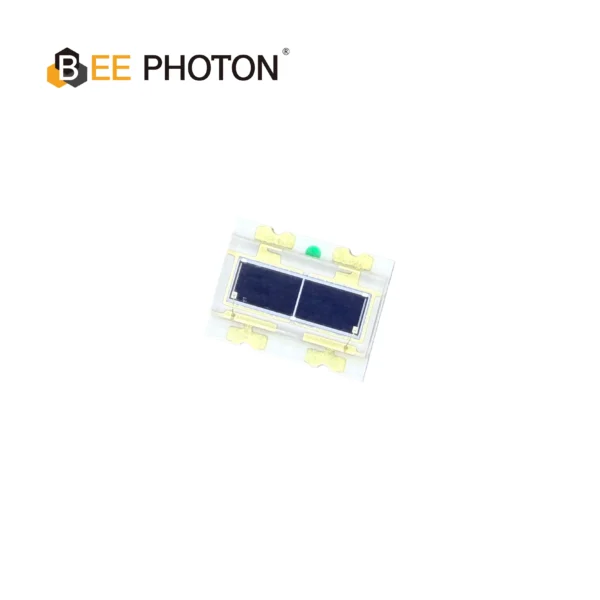
Si PIN Photodiode Array PDCA02-602
The Bee Photon PDCA Series is engineered specifically as a Background Suppression Photodiode to solve complex detection challenges in industrial environments. By utilizing a high-precision two-segment architecture (PD A and PD B), this device allows for differential signal processing, effectively filtering out background interference. It is the premier choice for manufacturers designing reliable background suppression optical switches and proximity sensors.
FAQ: Quick Answers for Optical Design Engineers
Is an 855nm NIR LED visible to the human eye?
Not for practical illumination purposes, but yes, you can see a very faint red glow if you look directly at the emitter in a completely dark room. This occurs because the wide tail of the LED’s spectral emission curve slightly bleeds into the extreme edge of human vision (which ends around 780nm). An 855nm NIR LED will have a slightly less visible red glow than a standard 850nm LED, but it is not completely covert like a 940nm emitter.
Can I replace an 850nm LED with an 855nm NIR LED directly?
In most cases, yes, the electrical parameters are almost identical. The forward voltage of an 855nm NIR LED is typically around 1.5V to 1.7V, which matches standard 850nm drivers. However, if your system uses a very narrow optical filter, you must verify that the 5nm shift does not push your emitter’s output outside the filter’s transmission band.
What makes an 855nm NIR LED different from a laser diode?
A laser diode emits coherent, highly monochromatic light with a spectral width (FWHM) of less than 1nm. An 855nm NIR LED emits incoherent light over a broader spectral width (typically 15nm to 30nm). LEDs are far less sensitive to electrostatic discharge (ESD), have longer lifespans, do not require complex safety certifications, and are significantly more cost-effective for B2B industrial sensors.
Where can I buy a high-quality 855nm NIR LED?
If you are sourcing an 855nm NIR LED for a precision industrial product, you should partner with a specialized optoelectronics manufacturer. Standard catalog distributors often carry generic illumination LEDs, but high-accuracy point sources require specialized binning and testing.
You can find a wide range of reliable, industrial-grade light sources and matched photodetectors directly through BeePhoton.
Getting Your Optical Design Right the First Time
Choosing between 850nm and 855nm is not just about choosing a number on a datasheet. It is about understanding how your system handles thermal drift, optical noise, and light collimation. If you are building a simple security camera, standard 850nm is often fine. But if you are building an encoder, a laser rangefinder alignment system, or a high-precision medical sensor, utilizing an 855nm NIR LED point source will save you countless hours of troubleshooting down the road.
At BeePhoton, we help R&D teams design, prototype, and manufacture custom optical sensor configurations. Whether you need help selecting a narrow-beam emitter, matching a photodiode to your specific wavelength, or sourcing high-reliability infrared light sources, our engineering team is here to help.
Do you have a challenging optical design on your desk?
Reach out to us directly on our contact page or send an email to our engineering desk at info@photo-detector.com with your project specifications. We can assist with custom packaging, specialized wavelength binning, and rapid prototyping to help you get your sensor to market with confidence.